Volkswagen Golf / Golf GTI / Golf Variant. Manual - part 395


  Index      Volkswagen     Volkswagen Golf / Golf GTI / Golf Variant - service repair manual 2013 year


Search            copyright infringement  


Content   ..  393  394  395  396   ..


Volkswagen Golf / Golf GTI / Golf Variant. Manual - part 395


5 - Screw

❑ 2.5 Nm
❑ Quantity: 2

6 - Spreader Plug

❑ Replace damaged or deformed spreader plug.

7 - Right Driver Side Impact Absorber

❑ Removing and installing. Refer to

⇒ “4.5 Driver Side Impact Absorber, Removing and Installing”, page 232

 .

8 - Screw

❑ 4.5 Nm

4.3

Crash Bolster, Removing and Installing

Special tools and workshop equipment required
♦ Torque Wrench 1331 5-50Nm - VAG1331-
Removing
– If installed, remove the knee airbag with igniter. Refer to

⇒ “9.2 Knee Airbag with Igniter, Removing and Installing”,

page 157

 .

– Remove the driver side footwell vent. Refer to ⇒  Heating,

Ventilation and Air Conditioning; Rep. Gr.  87 ; Air Routing;

Overview - Air Routing and Air Distribution in Passenger Com‐

partment .

– Remove the Data Bus on Board Diagnostic Interface - J533- .

Refer to ⇒  Electrical Equipment; Rep. Gr.  97 ; Control Mod‐

ules; Component Location Overview - Control Modules .

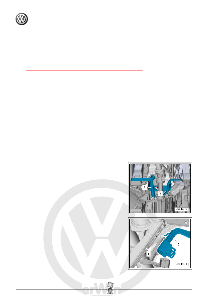
– Remove the bolt -2-, disengage the crash bolster -1- and guide

it out.

Installing
Install in reverse order of removal while paying attention to the

following:

– Engage the crash bolster -2- on the central tube -1- -arrow-

and fasten.

Tightening Specifications
♦ Refer to

⇒ “4.1 Overview - Instrument Panel Central Tube”, page 225

4.4

Instrument Panel Central Tube, Remov‐

ing and Installing

Special tools and workshop equipment required
♦ Torque Wrench 1331 5-50Nm - VAG1331-
♦ Torque Wrench 1783 - 2-10Nm - VAG1783-

Note

It may be helpful to make drawings or take photos of any wires

that are going to be loosened, removed and then installed. This

assures the wires will be reconnected correctly.

Removing
– Remove the left plenum chamber cover. Refer to ⇒  Body Ex‐

terior; Rep. Gr.  50 ; Bulkhead; Overview - Plenum Chamber

Cover .

– Remove the bolt -1- for the brace and central tube from the

plenum chamber bulkhead.

– Remove the instrument panel. Refer to

⇒ “3.6 Instrument Panel, Removing and Installing”,

page 213

 .

– If installed, remove the knee airbag with igniter. Refer to

⇒ “9.2 Knee Airbag with Igniter, Removing and Installing”,

page 157

 .

– Remove the driver side footwell vent. Refer to ⇒  Heating,

Ventilation and Air Conditioning; Rep. Gr.  87 ; Air Routing;

Overview - Air Routing and Air Distribution in Passenger Com‐

partment .

– Remove the driver side impact absorber, if installed. Refer to

⇒ “4.5 Driver Side Impact Absorber, Removing and Installing”,

page 232

 .

– Remove the bolts -1 and 2-.
– Disengage the bracket -3- for the control module, and the relay

and fuse carrier on the instrument panel central tube.

– Unbolt steering column from the instrument panel central tube

and lay it on the floor of the vehicle. Refer to ⇒  Suspension,

Wheels Steering; Rep. Gr.  48 ; Steering Column; Steering

Column, Removing and Installing .

– Remove the crash bolster. Refer to

⇒ “4.3 Crash Bolster, Removing and Installing”, page 228

 .

– If equipped, remove the Access/Start System Interface -

J965- . Refer to ⇒  Electrical Equipment; Rep. Gr.  97 ;

Component Location Overview - Control Modules .

– Release the expanding rivet -1- and remove it upward.
– Remove the intermediate piece for the defroster air vent -3-

from the instrument panel central tube.

– Unclip and remove the intermediate piece for the center vent

-2- from the heater and A/C unit.

– Remove the nut -1- from the central tube ground connection

-2- and free up the wires.

– Remove the footwell vent on the front passenger side. Refer

to ⇒  Heating, Ventilation and Air Conditioning; Rep. Gr.  87 ;

Air Routing; Overview - Air Routing and Air Distribution in Pas‐

senger Compartment .

– Remove the A/C unit bolts -arrows-.

– Push the carpet near the threaded connection to the side and

remove the left and right bolt -2- for the instrument panel cen‐

tral tube support.

Note

Mark height and side position on instrument panel central tube for

reinstallation.

Note

Mark the height and side position of the central tube in the vehicle

around the left and right nut -1- as well as the bolt -2- with a scrib‐

er.

– Remove the bolt -1- from the instrument panel central tube.
– Remove the nut -2- for the instrument panel central tube from

the left and right A-pillar.

– Unclip, disengage and free up the wires from the instrument

panel central tube.

– Remove the wiring harness bracket -2- from the instrument

panel central tube -1-.

– Loosen the instrument panel central tube -1- and pull it slightly

to the rear.

– Carefully lift the instrument panel central tube -1- out of the

vehicle with the help of a second technician. Pay attention to

the wiring harnesses.


Content   ..  393  394  395  396   ..