Volkswagen Golf / Golf GTI / Golf Variant. Manual - part 377
9
Knee Airbags
⇒ “9.1 Overview - Knee Airbag”, page 156
⇒ “9.2 Knee Airbag with Igniter, Removing and Installing”,
9.1
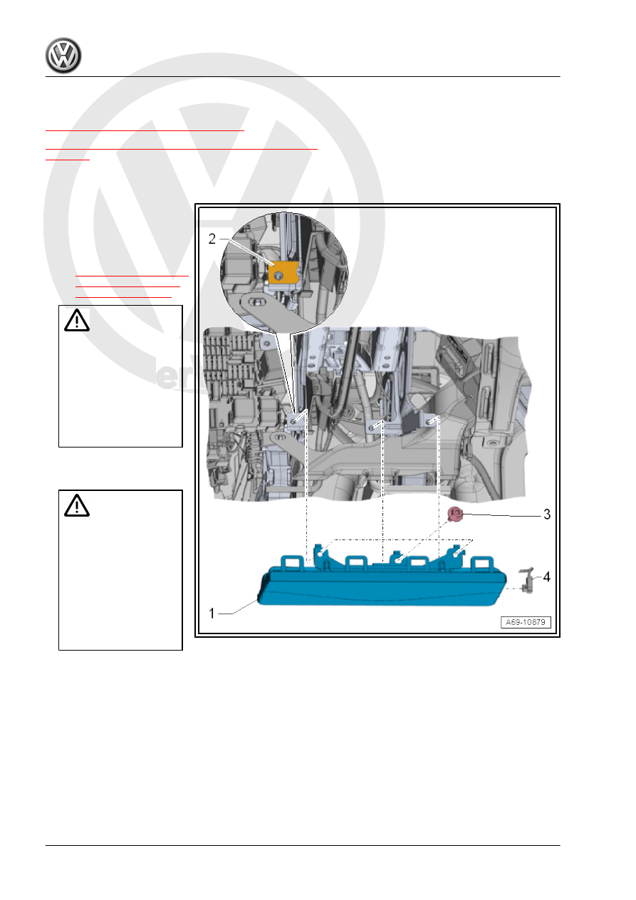
Overview - Knee Airbag
1 - Knee Airbag
❑ With the Driver Knee
Airbag Igniter - N295-
❑ Removing and instal‐
ling. Refer to
.
Caution
The risk of damaging the
knee airbag surface due
to mechanical stress is to
be prevented.
♦
After finishing work per‐
form a visual inspection if
the surface of the knee
airbag especially along
the area of the perfora‐
tion is undamaged.
2 - Attachment Point
❑ For the knee airbag
Caution
Avoid malfunctions due
to faulty ground connec‐
tions.
♦
Mounting thread and
contact surface must be
free of paint, coating, and
corrosion.
♦
The threaded connection
serves as a ground con‐
nection for the knee air‐
bag.
3 - Screw
❑ 8 Nm
❑ Quantity: 3
4 - Connector
❑ For the Driver Knee Airbag Igniter - N295-