Volkswagen Golf / Golf GTI / Golf Variant. Manual - part 239


  Index      Volkswagen     Volkswagen Golf / Golf GTI / Golf Variant - service repair manual 2013 year


Search            copyright infringement  


Content   ..  237  238  239  240   ..


Volkswagen Golf / Golf GTI / Golf Variant. Manual - part 239


Installing
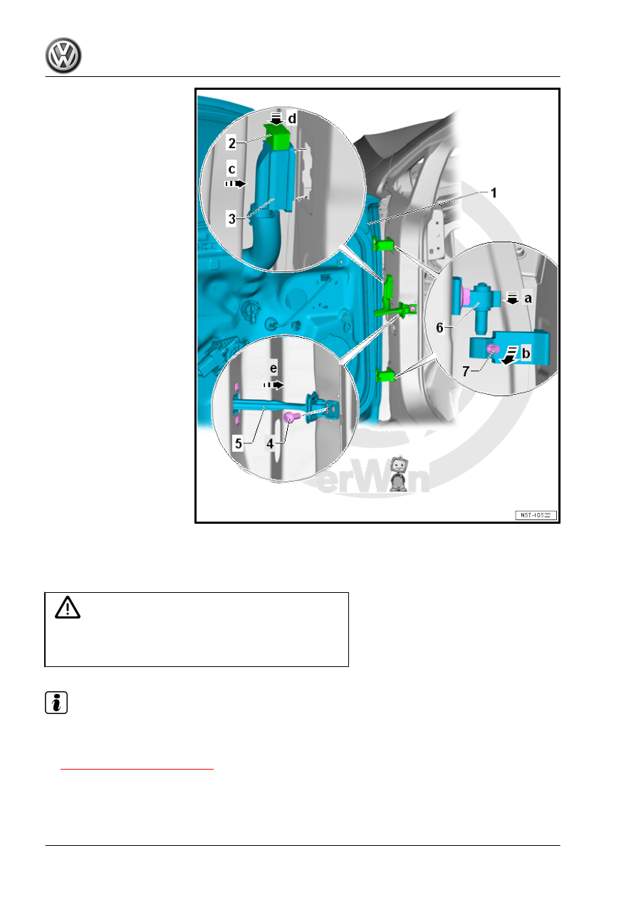
Install in reverse order of removal. Pay attention to the following

when installing:

Caution

The door strap bracket must be folded in toward the inside of

the vehicle (to prevent damaging the paint) before installing the

front door.

Note

The hinge arms must be flush with each other after engaging the front door.

– Adjust the front door -1-. Refer to

⇒ “1.5 Door, Adjusting”, page 89

 .

– Pay attention the gap dimensions for the front door -1-. Refer

to ⇒ Body Repair; Rep. Gr.  00 ; Body Gap Dimensions; Center

Body .

Tightening Specifications
Refer to 

⇒ “1.1 Overview - Door”, page 79

1.5

Door, Adjusting

Special tools and workshop equipment required
♦ Wrench - Door Adjusting - 3320-
♦ Door Adjusting Wrench - Joint - 3320/1-
♦ Wrench - Door Adjusting - Box Wrench - 3320/2-
♦ Wrench - Door Adjusting - Box Wrench - 3320/3-
♦ Torque Wrench 1331 5-50Nm - VAG1331-
♦ Cylinder Head Bolt Socket - 3410-
♦ Gauge - Gap Adjustment - 3371-
♦ Trim Removal Wedge - 3409-

Caution

This procedure contains mandatory replaceable parts. Refer

to component overview prior to starting procedure.

Mandatory Replacement Parts
♦ Bolts - Door Hinge to Body (Loosening one time to adjust the

door is permitted. Always replace afterward.)

♦ Bolt - Door Hinge to Door (Loosening one time to adjust the

door is permitted. Always replace afterward.)

Note

The following describes adjusting the left front door. Adjusting the right front door is identical.

The vehicle must be on the ground in order to adjust the door.

The front door is properly adjusted when there is an overall even gap dimension when closed. It is not too

far inward or outward. And the contours align.

Checking the gap dimensions. Refer to ⇒ Body Repair; Rep. Gr.  00 ; Body Gap Dimensions; Center Body .

Perform corrosion protection measures on the hinges and the bolts after assembling or adjusting.

Gap Dimensions, Adjusting
For correct gap dimension adjustment, screws -2, 3, 5, and 6- at

the A-pillar must be loosened.
– For the bolt -3-, loosen and lower the driver side fuse box.

Refer to ⇒  Electrical Equipment; Rep. Gr.  97 ; Relay Carriers,

Fuse Panels and E-Boxes; Relay and Fuse Carrier Behind In‐

strument Panel on Driver Side, Removing and Installing .

– For the bolt -3-, the glove compartment on the front passenger

side must be removed. Refer to ⇒  Body Interior; Rep. Gr.  68 ;

Storage Compartments and Covers; Glove Compartment, Re‐

moving and Installing .

– Remove the A-pillar lower trim panel to access the bolt -6-.

Refer to ⇒  Body Interior; Rep. Gr.  70 ; Passenger Compart‐

ment Trim; A-Pillar Trim Panel, Removing and Installing .

Flush Dimension Adjustment
The bolts -4 and 7- must be loosened in order to correctly adjust

the flush dimension.
Use the Wrench - Door Adjusting - 3320- with the respective bit

for this.

Note

Other measures, such as aligning the front door upward, are not effective. Later pressure will cause the front

door to sag again.

Adjust the catch. Refer to 

⇒ “1.6 Catch, Adjusting”, page 91

 .

Note

After replacing the A-pillar, the other tightening specification must be observed. Refer to

⇒ “1.1 Overview - Door”, page 79

 .

Tightening Specifications
Refer to 

⇒ “1.1 Overview - Door”, page 79

1.6

Catch, Adjusting

Special tools and workshop equipment required
♦ Torque Wrench 1331 5-50Nm - VAG1331-

Note

The threaded plate -1- of the catch in the pillar is secured differently than before.

The arch outside the threaded plate is welded securely to the pillar. The bars to the threaded plate are

malleable plastic.

More force is needed to move the catch -2- when the bolts -3- are loose.


Content   ..  237  238  239  240   ..