Volkswagen Golf / Golf GTI / Golf Variant. Manual - part 132
DTC /
Descrip‐
tion
Monitor
Strategy
Descrip‐
tion
Malfunction Crite‐
ria and Threshold
Value
Secondary Parame‐
ters with Enable
Conditions
Monitor‐
ing Time
Length
MIL Il‐
lum.
Component Diag‐
nostic Procedure
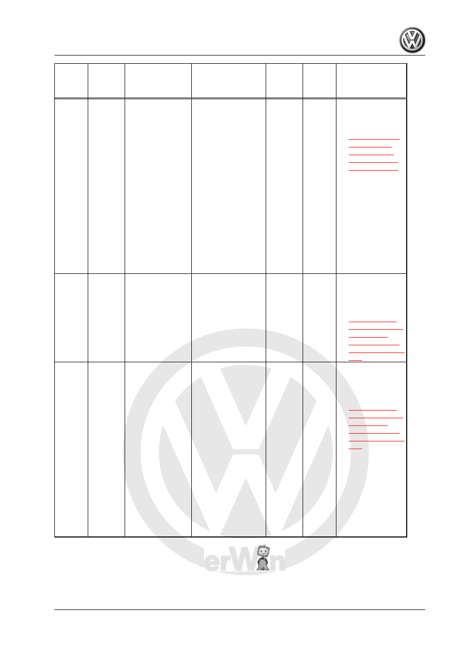
P0011
"A"
Cam‐
shaft
Position
- Timing
Over-
Ad‐
vanced
or Sys‐
tem Per‐
for‐
mance
Bank 1
VVT Ac‐
tuator In‐
take Ra‐
tionality
Check
• Camshaft posi‐
tion deviation >
10.0° CRK
• Modeled oil tem‐
perature -40 –
160° C
• Engine speed
608 – 6,016 RPM
• Camshaft posi‐
tion n.a.
• Camshaft posi‐
tion adjustment
active
• Catalyst heating
not active
• Camshaft posi‐
tion deviation in‐
tegrator ( actual
vs. setpoint posi‐
tion) >= 9.00 –
12.00° CRK
• 0
FTP75:
250 s
• Contin‐
uous
• 2
DCY
– Check the Cam‐
shaft Adjust‐
ment Valve 1 -
N205- . Refer to
.
P0013
"B"
Cam‐
shaft
Position
Actuator
Control
Circuit/
Open
Bank 1
Variable
Valve
Timing
(VVT) Ex‐
haust Ac‐
tuator
open cir‐
cuit
• Output voltage,
lower range
1.92 – 2.21 V
• Output voltage,
upper range
2.85 – 3.25 V
(hardware val‐
ues)
• Actuator com‐
manded off
• 2.0 s
• Con‐
tinu‐
ous
• 2
DCY
– Check the Ex‐
haust Camshaft
Adjustment
Valve 1 - N318- .
Refer to
P0014
"B"
Cam‐
shaft
Position
- Timing
Over-
Ad‐
vanced
or Sys‐
tem Per‐
for‐
mance
Bank 1
Variable
Valve
Timing
(VVT) Ex‐
haust Ac‐
tuator
Rationali‐
ty Check
• Difference be‐
tween target
and actual po‐
sition > 10.00°
CRK
• Modeled oil tem‐
perature -40 –
160° C
• Engine speed
608 – 6,016 RPM
• Camshaft posi‐
tion n.a.
• Camshaft posi‐
tion adjustment
active
• Catalyst heating
not active
• Camshaft posi‐
tion deviation in‐
tegrator ( actual
vs. setpoint posi‐
tion) >= 9.00 –
12.00° CRK
• 0
FTP75:
450 s
• Contin‐
uous
• 2
DCY
– Check the Ex‐
haust Camshaft
Adjustment
Valve 1 - N318- .
Refer to
GTI 2014 ➤
Generic Scan Tool - Edition 04.2015
3. Diagnosis and Testing
201