Volkswagen Golf / Golf GTI / Golf Variant. Manual - part 33
– Remove the headlamp. Refer to
⇒ “1.2 Headlamp, Removing and Installing”, page 101
.
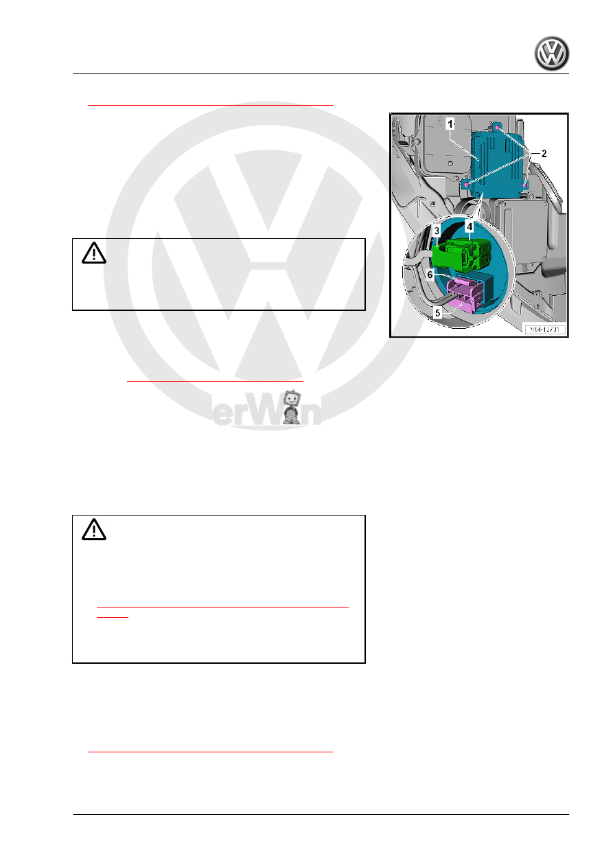
– Remove the screws -2-.
– Remove the Left Hid Headlamp Control Module - J343- -1-
from the headlamp.
– Push the release buttons -4 and 6-.
– Disconnect the connectors -3 and 5-.
Installing
Install in the reverse order of removal while paying attention to
the following:
Caution
Make sure the seal fits correctly when installing the HID head‐
lamp control module. Water getting in the headlamp will cause
damage.
– Make sure the seal between the control module and the head‐
lamp is not damaged.
Tightening Specifications
♦ Refer to
⇒ “1.1 Overview - Headlamp”, page 92
1.18
Left/Right Headlamp Power Output
Stage -J667- / -J668- , Removing and
Installing
The removal and installation is described for the left side. Re‐
moving and installing on the right side is identical.
The Left Headlamp Power Output Stage - J667- / Right Headlamp
Power Output Stage - J668- is only installed with HID headlamps
with cornering lamps.
WARNING
High voltage poses a life-endangering risk, injury risk and en‐
vironmental hazard.
♦ Pay attention to usage and safety information for HID
headlamps. Refer to
⇒ “1.3 HID Headlamps Usage and Safety Precautions”,
♦ It is necessary to disconnect the battery wire strap before
working on HID headlamp components. These parts are
marked with yellow high voltage symbols.
Removing
– Turn off the ignition and all electrical equipment.
– Remove the ignition key, if equipped.
– Remove the headlamp. Refer to
⇒ “1.2 Headlamp, Removing and Installing”, page 101
.
– Remove the screws -2-.
– Remove the Left Headlamp Power Output Stage - J667- -1-
from the headlamp.