Volkswagen Golf / Golf GTI / Golf Variant. Manual - part 15
90 – Instruments
1
Instrument Cluster
1.1
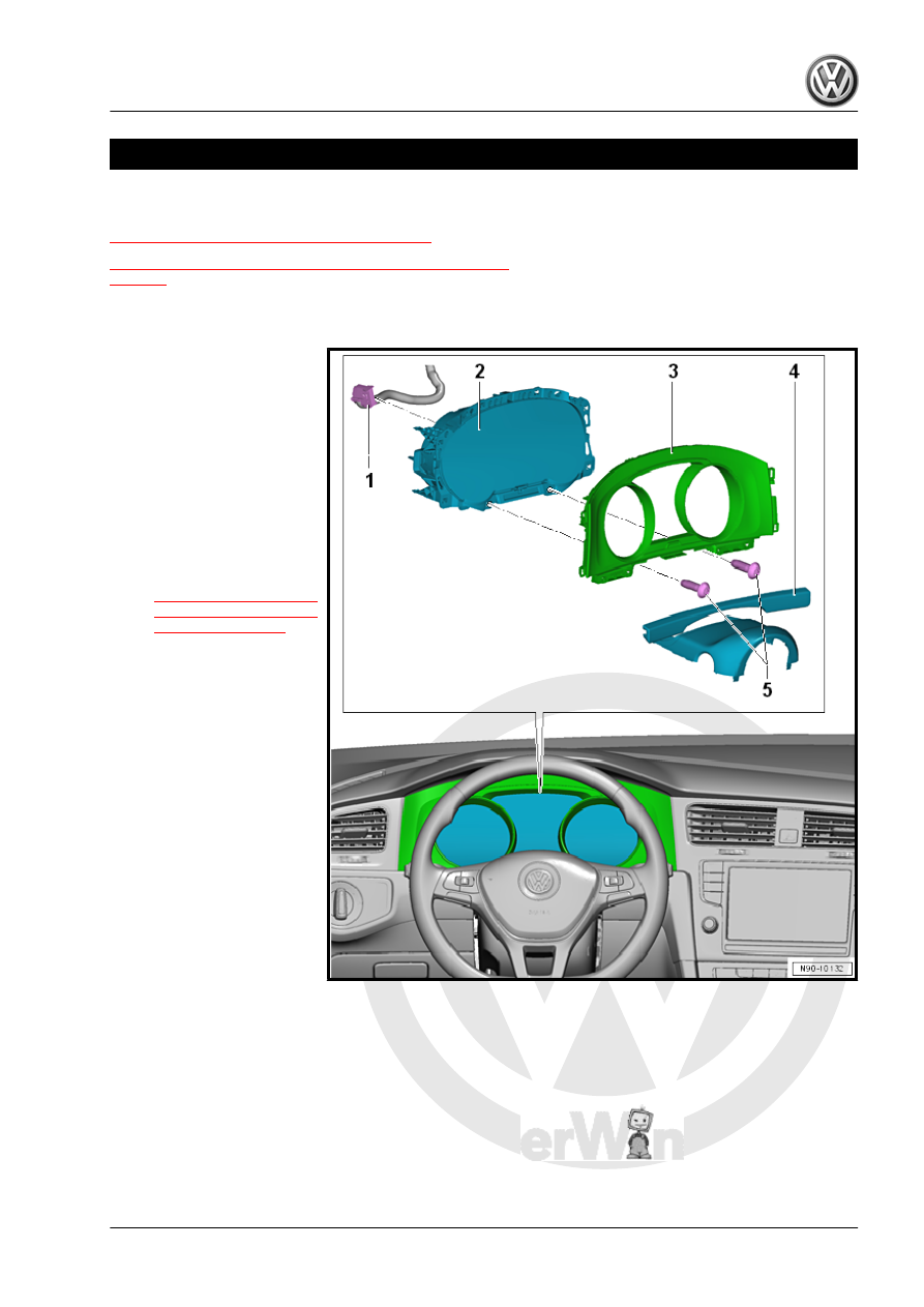
Overview - Instrument Cluster
1 - Connector
❑ For the instrument clus‐
ter
2 - Instrument Cluster - KX2-
❑ With Instrument Cluster
Control Module - J285-
❑ If a LED indicator lamp
or instrument cluster il‐
lumination is faulty, the
instrument cluster must
be replaced
❑ Removing and instal‐
ling. Refer to
3 - Instrument Cluster Trim
❑ Removing and instal‐
ling. Refer to ⇒ Body
Interior; Rep. Gr. 70 ;
Instrument Panel; In‐
strument Cluster Trim,
Removing and Instal‐
ling .
4 - Upper Steering Column
Trim Panel
❑ Overview. Refer to ⇒
Body Interior; Rep. Gr.
68 ; Storage Compart‐
ments and Covers;
Overview - Steering
Column Trim Panel .
5 - Screw
❑ 3 Nm
❑ Quantity: 2
1.2
Instrument Cluster - KX2- , Removing
and Installing
General Information
All indicator lamps in the Instrument Cluster - KX2- have LEDs.
LEDs cannot be replaced separately if faulty. The Instrument
Cluster - KX2- must be replaced.
The following components are integrated inside the Instrument
Cluster - KX2- :