Volkswagen Golf / Golf GTI / Golf Variant. Manual - part 5


  Index      Volkswagen     Volkswagen Golf / Golf GTI / Golf Variant - service repair manual 2013 year


Search            copyright infringement  


Content   ..  3  4  5  6   ..


Volkswagen Golf / Golf GTI / Golf Variant. Manual - part 5


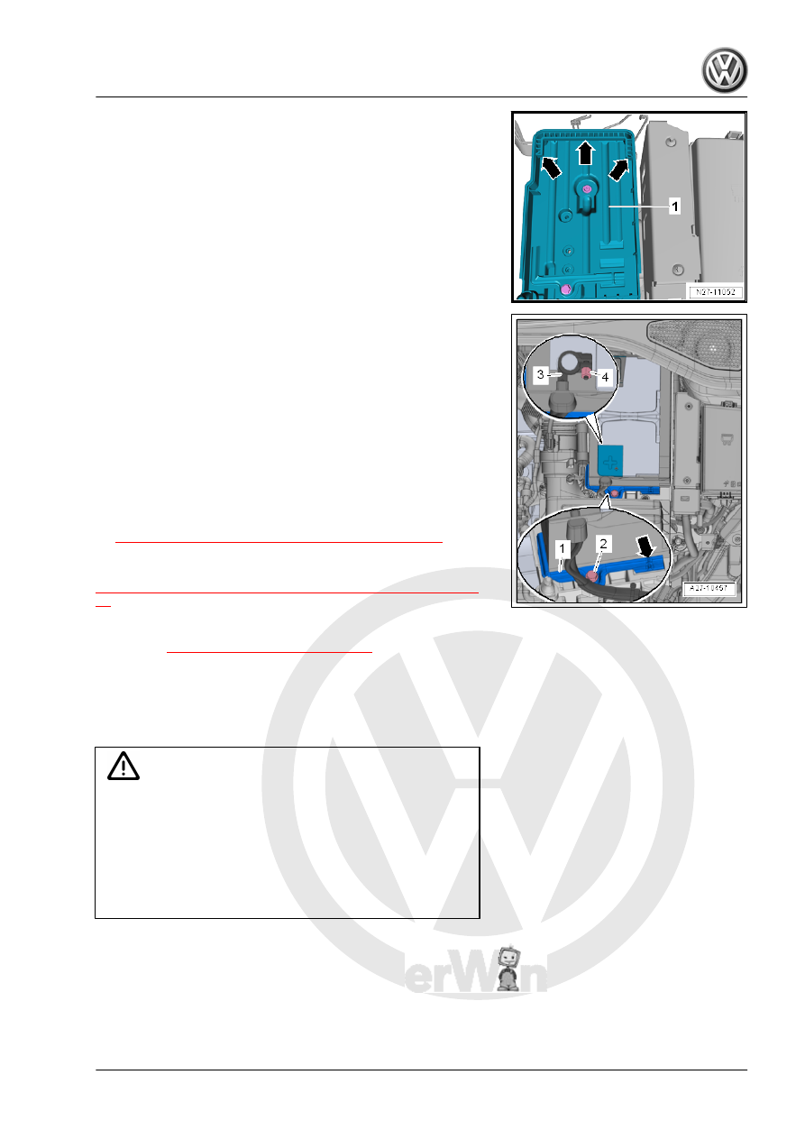
– Insert the Battery - A- into the battery tray -1- so that the battery

base strip touches the rear and side stop -arrows-.

• It must not be possible to slide the Battery - A- rearward or to

the side.

– Install the bracket -1-.
• The tab -arrow- on the bracket -1- must fit into the opening on

the battery clamping strip.

– Tighten the bolt -2- for the bracket -1-.
– Checking the Battery - A- for secure seating.
Turn off the Ignition and All Electrical Consumers, and Connect

the Battery - A- in the Following Sequence:
– Install the battery positive cable terminal -3- on the battery

positive terminal “+”.

– Tighten the nut -4-.
– Connect the Battery - A- . Refer to

⇒ “1.3 Battery, Disconnecting and Connecting”, page 9

 .

When the battery is replaced the Battery Monitoring Control Mod‐

ule - J367- must be adapted. Refer to

⇒ “1.8  Battery Monitoring Control Module J367 , Adapting”, page

12

 .

Tightening Specifications
♦ Refer to 

⇒ “1.1 Overview - Battery”, page 6

1.3

Battery, Disconnecting and Connecting

Special tools and workshop equipment required
♦ Torque Wrench 1783 - 2-10Nm - VAG1783-

Caution

Follow  all  safety  precautions  when  working  on  pyrotechnic

components:

♦ When working on pyrotechnic components (airbag, belt

tensioner), it is necessary to disconnect the battery with

the ignition turned on, contrary to the following descrip‐

tion . Refer to ⇒  Body Interior; Rep. Gr.  00 ; Safety

Precautions; Pyrotechnic Components Safety Precau‐

tions .

Disconnecting
– Turn off the ignition and all electrical equipment.
– Remove the ignition key, if equipped.
– Open the heat protection sleeve cover.
– Open the cover -1- over the battery negative terminal.

– Loosen the nut -3- several turns and remove the battery

ground cable terminal clamp -2- from the battery terminal.

Connecting
Pay attention to the following when disconnecting the Battery -

A- .

– Release and disconnect the connector -2- from the Battery

Monitoring Control Module - J367- -3-.

– Install the battery ground cable terminal clamp by hand on the

battery negative terminal “–”.

– Tighten the nut -1- to the tightening specification.
– Reconnect the connector -2- to the Battery Monitoring Control

Module - J367- .

– Turn on the ignition.
– Check the time and if necessary adjust.
– Window, open and close all the way.
– Then, with the windows closed, pull the power window switch

until the relay audibly switches.

– Check the window regulator convenience switch.
While comfort switching is operated, window must close without

holding the power window switch.

Note

After connecting the power supply, the ASR/ESP Indicator Lamp

- K155- may only go out after the vehicle has been driven a few

yards.

Tightening Specifications
♦ Refer to 

⇒ “1.1 Overview - Battery”, page 6

1.4

Battery Tray, Removing and Installing

Special tools and workshop equipment required
♦ Torque Wrench 1331 5-50Nm - VAG1331-
Removing
– If necessary, remove the air filter housing. Refer to ⇒  Rep.

Gr.  23 ; Air Filter; Air Filter Housing, Removing and Installing

or ⇒  Rep. Gr.  24 ; Air Filter; Air Filter Housing, Removing and

Installing .

– Remove the Battery - A- . Refer to

⇒ “1.2 Battery, Removing and Installing”, page 7

 .

– Free up the wiring harness from the battery tray -arrows-.

– Remove the bolts and nut -2-.
– Remove the battery tray -1-.
Installing
Install in reverse order of removal.
Tightening Specifications
♦ Refer to 

⇒ “1.1 Overview - Battery”, page 6

1.5

Battery, Checking

Checking the battery. Refer to ⇒  Electrical Equipment General

Information; Rep. Gr.  27 ; Battery, Checking .
The Battery - A- is checked in the Data Bus On Board Diagnostic

Interface - J533- OBD using the Vehicle Diagnostic Tester in

“Guided Fault Finding” mode.

1.6

Battery, Charging

Battery charging. Refer to ⇒  Electrical Equipment General Infor‐

mation; Rep. Gr.  27 ; Battery, Charging .

1.7

Ground Cable with Battery Monitoring

Control Module - J367- , Removing and

Installing

Special tools and workshop equipment required
♦ Torque Wrench 1331 5-50Nm - VAG1331-
Removing
– Remove the Battery - A- . Refer to

⇒ “1.2 Battery, Removing and Installing”, page 7

 .

– Release and disconnect the connector -2- from the Battery

Monitoring Control Module - J367- -3-.

– Remove the nut -1- for the ground cable -2-.
– Remove the nut -3- and remove the ground cable with Battery

Monitoring Control Module - J367- -4-.

Installing
Install in the reverse order of removal while paying attention to

the following:
– Adapt the Battery Monitoring Control Module - J367- . Refer

to

⇒ “1.8  Battery Monitoring Control Module J367 , Adapting”,

page 12

 .

Tightening Specifications
♦ Refer to 

⇒ “1.1 Overview - Battery”, page 6

1.8

Battery Monitoring Control Module -

J367- , Adapting

After installing a new start battery or a new Battery Monitoring

Control Module - J367- the Battery Monitoring Control Module -

J367- must be adapted.
– Adapt the Battery Monitoring Control Module - J367- using the

Vehicle Diagnostic Tester .


Content   ..  3  4  5  6   ..