Volkswagen Golf / Golf GTI / Jetta. Manual - part 915


  Index      Volkswagen     Volkswagen Golf / Golf GTI / Jetta - service repair manual 1999-2005 year


Search            copyright infringement  


Content   ..  913  914  915  916   ..


Volkswagen Golf / Golf GTI / Jetta. Manual - part 915


01-436


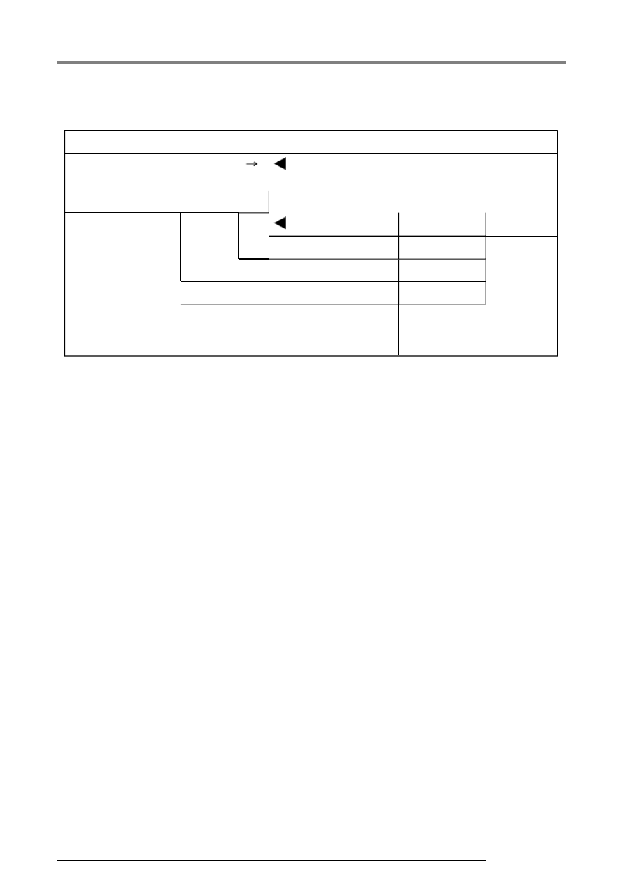
Break down of display content for display group number 006  

Display group 006  

Read Measuring Value Block 
6  


 Indicated on 

display  


xxx  

xxx  

xxx  

xxx     


1  

2  

3  

4  

 Display zones  

Specification  Evaluation 


Blank  


Blank  


Blank  


Check bus  

Bus OK.  

Bus not OK.  


Driver's side seat adjustment, On Board Diagnostic (OBD)

13/2/2005

01-437


Evaluating display group number 006  

Display 

zone  

Description   Display  

Corrective action  

1   

Check bus  

Bus OK.  

Bus not 

OK.  

- Visual check of wiring 

- Check that connections of relevant current 
circuit are correctly connected and seated 
securely while simultaneously observing display 

- If the display does not change when operating, 
repair malfunction or replace relevant 
component 

- If no changes occur, separate all door main 
connectors and reconnect one after the other 
again 

- Observe measured value block 

- If display changes, replace relevant control 
module 

- Erase DTC memory 

- Perform functional check 

- Check DTC memory again 

Driver's side seat adjustment, On Board Diagnostic (OBD)

13/2/2005

Select a topic


01 - On Board Diagnostic (OBD)


On Board Diagnostic (OBD) through m.y. 2001


Tools


VAS 5051 or VAG 1551, connecting


On Board Diagnostic (OBD) from m.y. 2002


General information 


Climatronic On Board Diagnostic (OBD) through m.y. 2001


General information


Climatronic - On Board Diagnostic (OBD), initiating and checking 
control module versions


Diagnostic Trouble Code (DTC) memory, checking (function 02)


Diagnostic Trouble Code (DTC) table


Output Diagnostic Test Mode (DTM) (function 03)


Basic setting (function 04)


Diagnostic Trouble Code (DTC) memory, erasing (function 05)


End output (function 06)


Climatronic Control Module -J255-, coding (function 07)


Read Measuring Value Block (function 08)


80 - Heating, Ventilation


Heating and ventilation system, servicing


Air outlets, removing


Heating and ventilation controls, removing and installing


Ventilation system, checking


Heating and ventilation unit, assembly


Heating and ventilation controls, assembly


Cables, installing and adjusting


87 - Air conditioning


Manual A/C


Heating and A/C components in passenger compartment, servicing


Heating and A/C controls, removing and installing


Heating and A/C controls, assembly


Cables, installing and adjusting


Heating and A/C components in engine compartment, servicing


Climatronic


General information


On Board Diagnostic (OBD)


Components, checking and adjusting with VAS 5051


A/C control head -E87-, function


Climatronic components in passenger compartment, servicing


A/C control head-E87- with Climatronic control module -J255-, 
removing and installing


Air flap motors (for climate control regulation), replacing


Climatronic components in engine compartment, servicing


Heating and Air Conditioning

13/2/2005

A/C refrigerant system


Safety measures


A/C refrigerant R-134a, properties


Commercial designation


A/C refrigerant system, identification


A/C refrigerant system, component overview


A/C refrigerant system, replacing components


A/C refrigerant system, servicing


A/C pressure switch -F129-, checking


High pressure sensor -G65-, checking


Expansion valve, removing/assembly


Condenser, removing and installing


Heating and A/C unit, removing/assembly


A/C refrigerant system pressures and temperatures, checking


A/C refrigerant system, testing with pressure gauges


A/C refrigerant system, discharging


A/C refrigerant system, flushing with compressed air and nitrogen


A/C refrigerant system, evacuating and recharging


A/C refrigerant system, troubleshooting


Compressor noisy


A/C refrigerant system pressures, checking


A/C refrigerant system cooling performance, checking


A/C refrigerant system, checking for leaks


A/C refrigerant system, capacities


Refrigerant R-134a, capacity


Refrigerant (PAG) oil R-134a, identification


Refrigerant (PAG) oil R-134a, capacity


Refrigerant (PAG) oil R-134a, distribution


Compressor bracket, removing and installing


4-cylinder gasoline engine


6-cylinder engine


4-cylinder TDI engine


A/C clutch -N25- (Sanden), servicing


A/C clutch -N25- (Zexel), servicing


Additional Information 

System Overviews  

Other Topics 

A/C Refrigerant Pressure Switch/Sensor Operation


Heating and Air Conditioning

13/2/2005


Content   ..  913  914  915  916   ..