Volkswagen Golf / Golf GTI / Jetta. Manual - part 902
01-384
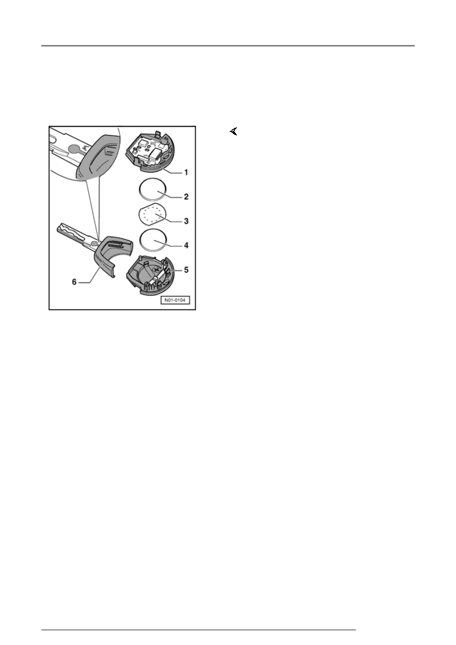
Installing
Note the polarity and correct position
when installing the batteries.
- Place the battery -4- with the
positive terminal downwards into
the sensor unit (positive terminal
is marked on housing).
- Now place the contact plate -3-
on the battery -4-.
- Place battery -2- with the positive
terminal downwards onto the
contact plate and secure.
- Place transmitter unit -1- and
transmitter unit -5- halves
together and clip to create one
remote transmitter assembly.
- Then engage the transmitter unit
with the main key.
Central locking system (vehicles without power windows), On Board Diagnostic ...
13/2/2005