Volkswagen Golf / Golf GTI / Jetta. Manual - part 343


  Index      Volkswagen     Volkswagen Golf / Golf GTI / Jetta - service repair manual 1999-2005 year


Search            copyright infringement  


Content   ..  341  342  343  344   ..


Volkswagen Golf / Golf GTI / Jetta. Manual - part 343


01-34


     Displayed is  

e.g. (1J0 907 379 D)  

Allocation of control module see 
Parts catalog  

 Electrical Wiring Diagrams, 

Troubleshooting & Component 
Locations binder
 

Coding control module 


Page 01-

58


 Operating instructions for Vehicle 

Diagnosis, Testing and Information 
System VAS 5051.
 

 The control module identification 

number. 

 System designation (ABS 20 IE) 

 Data BUS present. (CAN) 

 Control module code (03504). 

 Workshop code 

     Indicated on display  

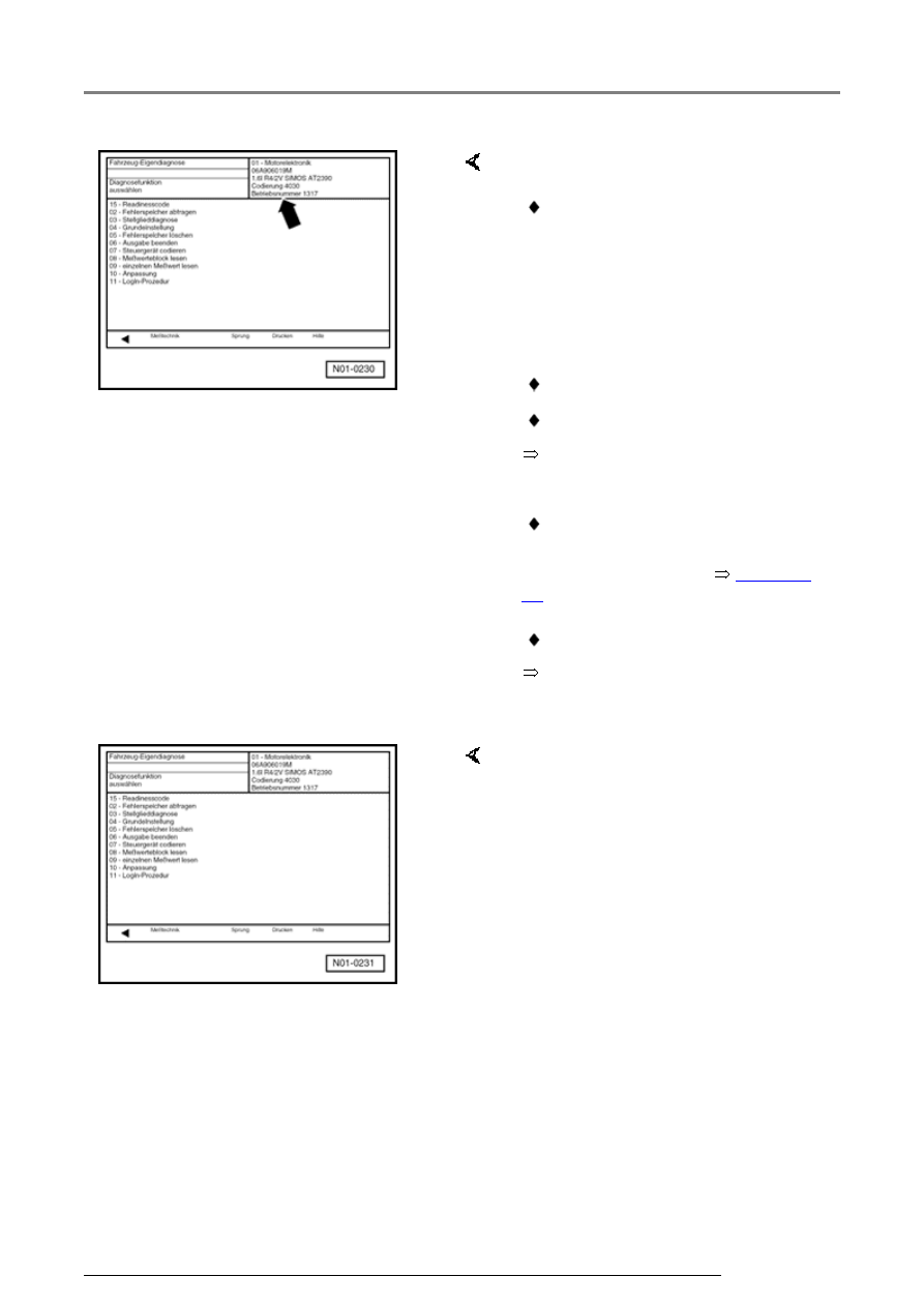
Select diagnostic function:  

At this point all diagnostic functions 
are available.  

For further measures see repair 
procedures.  

ABS ITT Mk 20 IE On Board Diagnostic (OBD) program

01-35


Diagnostic Trouble Code (DTC) table 


Note on DTC table:  

 When beginning OBD of the vehicle control modules, always start with function 

"Automatic test sequence" by pressing keys 0 and 0 because the control modules 
are interconnected with a data bus wire. This checks the DTC memories of the 
control modules in the vehicle.
 

 All the possible DTCs which can be recognized by the ABS control module -J104- 

and printed-out on V.A.G 1551 or VAS 5051, are listed on the following pages 
according to the 5-digit DTC.
 

 DTC appears (in the "Rapid data transfer" mode) only on the print-out.  

Example:  


DTC  

P code   DTC type code  

5-digit  

5-digit  

3-digit  

18256  

P1848  

035  

 The 5-digit P code which may appear next to the DTC, is for use with the On Board 

Diagnostic (OBD) II and may be disregarded.  

 The 3-digit DTC type code is a data code and may be disregarded, but the DTC type 

text is of use. 

 Before replacing components indicated as being faulty, check all the appropriate 

connectors, wiring and Ground connections using the wiring diagram  

 Electrical Wiring Diagrams, Troubleshooting & Component Locations binder  

 On completion of repairs always check the DTC memory with V.A.G 1551 Scan Too. 

or the tester VAS 5051 and erase. 

 Carry out road test exceeding 20 km/h (13 mph).  

 After the road test check DTC memory again.  

ABS ITT Mk 20 IE On Board Diagnostic (OBD) program

01-36


V.A.G 1551 
print-out 
 

Possible cause  

Repair  

No DTC 
recognized  

If "No DTC recognized" appears after carrying out repairs, On Board 
Diagnostic (OBD) is ended.  

If, despite "No DTC recognized" appearing in the display, the ABS 
system does not function properly, then proceed as follows:  

1. Carry out road test exceeding 20 km/h (13 mph),  

2. Again check DTC memory, if there is still no DTC stored,  

3. Continue troubleshooting without OBD and work through the 
complete Electrical check 


Page 01-102

 .  

ABS ITT Mk 20 IE On Board Diagnostic (OBD) program

01-37


V.A.G 
1551 print-
out 
 

Possible cause  

Repair  

00283  


Left front 
ABS wheel 
speed 
sensor -
G47-  

 Open circuit, short to positive or 

Ground, or loose contact in 
connections between left front 
ABS wheel speed sensor -G47- 
and ABS Control Module 
(w/EDL) -J104- 

- Check wiring and connections 
using wiring diagram 

- Perform electrical checks 

 from 


Page 01-102


 Damaged rotor or left front ABS 

wheel speed sensor -G47 

 Left front ABS wheel speed 

sensor windings -G47- faulty 

- Check left front ABS wheel speed 
sensor -G47- and rotor for damage 

- Replace rotor/speed sensor -G47- 


Repair Manual, Brake System, 

Repair Group 45; Removing and 
installing parts of ABS system on 
front and rear axles


If the malfunction occurs again:  


 ABS Control Module (w/EDL) -

J104- faulty 


Repair Manual, Brake System, 

Repair Group 45; Hydraulic unit, 
brake booster/brake master cylinder 
- Assembly overview; Removing 
and installing control module and 
hydraulic unit


- Replace ABS Control Module 
(w/EDL) -J104- 

ABS ITT Mk 20 IE On Board Diagnostic (OBD) program


Content   ..  341  342  343  344   ..