Volkswagen Golf / Golf GTI / Jetta. Manual - part 249
28-16
Camshaft Position (CMP) Sensor,
checking
Note:
Only gold-plated terminals may be used to
service the terminals in the Camshaft Position
(CMP) Sensor connector.
Special tools, materials and equipment
VAG 1526 or Fluke 83 Hand multimeter or VAG
1715 multimeter
VAG 1594 adapter set
VAG 1598/31 test box
Electrical Wiring Diagrams
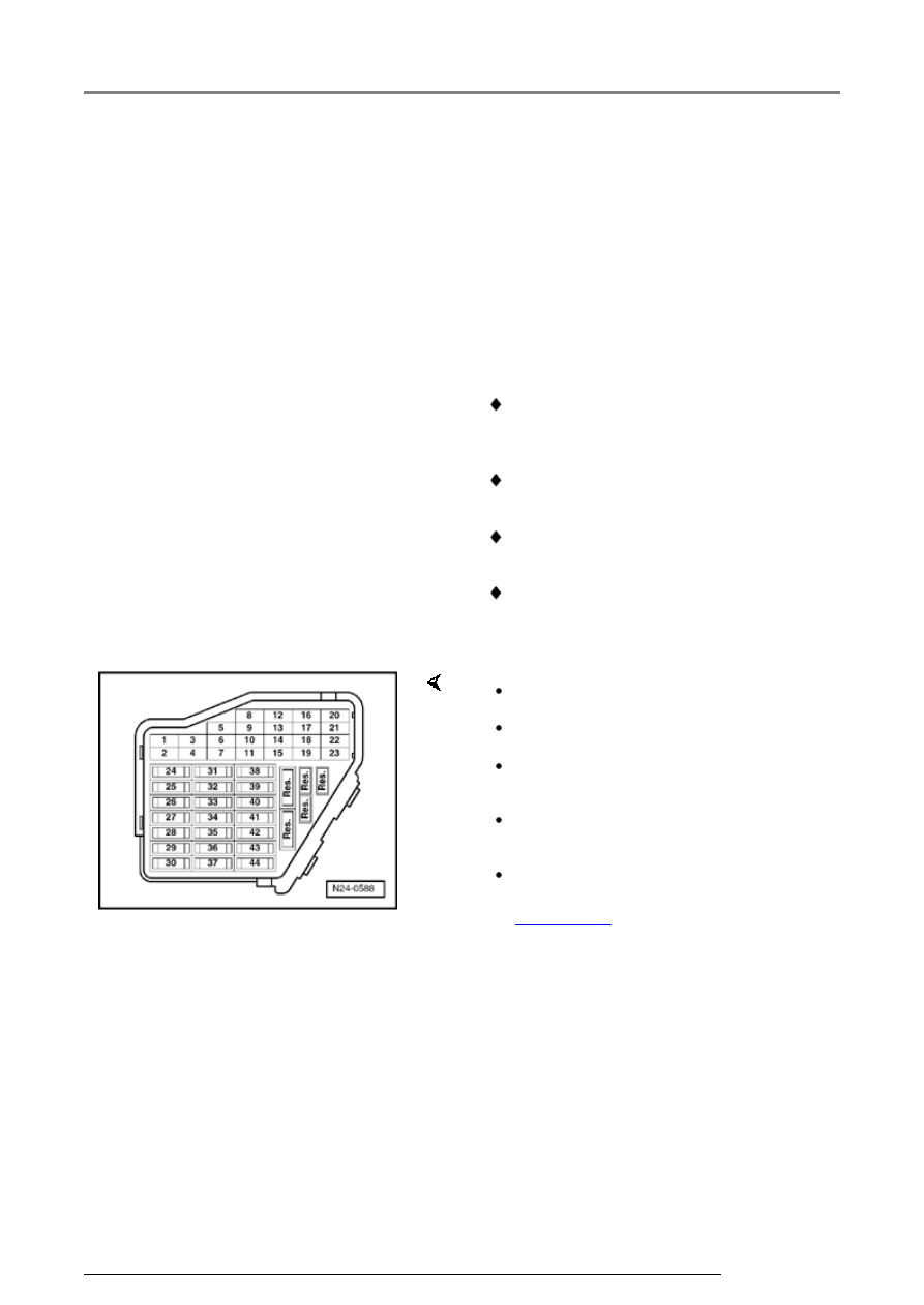
Test requirements
The fuses must be OK.
The battery voltage must be at least 11.5 V.
All electrical accessories, e.g. lights and rear
window defroster must be switched off.
If the vehicle is equipped with air conditioning,
it must be turned off.
Camshaft Position (CMP) Sensor malfunction
detected by On Board Diagnostic (OBD)
Page 01-23
.
Ignition system, servicing