Volkswagen Golf / Golf GTI / Jetta. Manual - part 196
 

  Index      Volkswagen     Volkswagen Golf / Golf GTI / Jetta - service repair manual 1999-2005 year


Search            copyright infringement  


Content   ..  194  195  196  197   ..


Volkswagen Golf / Golf GTI / Jetta. Manual - part 196


24-38


Components, checking 


Heated Oxygen Sensor (HO2S), 
checking


Note:  


 The vehicle must be raised to gain access to 

the Oxygen Sensor (O2S) connector. 


 Only gold plated terminals may be used to 

repair the terminals in the Oxygen Sensor 
(O2S) connectors.


Special tools and equipment  


Note:  

All functions which could previously be performed 
with VAG 1551/1552 can also be performed with 
the VAS 5051.
 

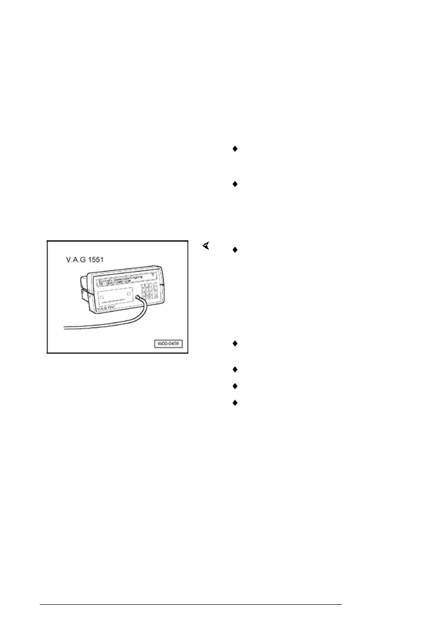
 VAG 1551 Scan tool (or VAG 1552) with VAG 

1551/3 adapter cable 

 VAG 1526 or Fluke 83 Hand multimeter or VAG 

1715 multimeter 

 VAG 1594 Adapter set 

 VAG 1598/31 Test box 

 Electrical Wiring Diagrams 

Components, checking

24-39


Test requirements  


 Electrical Wiring Diagrams, 

Troubleshooting & Component 
Locations
 

 The fuses must be OK. 

 The battery voltage must be at 

least 11.5 V. 

 All electrical accessories, e.g. 

lights and rear window defroster 
must be switched off. 

 If the vehicle is equipped with air 

conditioning, it must be switched 
off. 

 Selector lever must be in 

position "P" or "N" on vehicles 
with an automatic transmission. 

 Fuel Pump (FP) relay -J17- must 

be OK., checking: 

Components, checking

24-40


Test sequence  


-  Connect VAG 1551 Scan tool (or VAG 1552) 

and select engine electronics control module 
with "Address word" 01. Engine must be running 
at idle speed: ((VAG 1551 and Motronic Engine 
Control Module (ECM) -J220-, connecting and 
selecting 


Page 01-12

 ). 

Rapid data transfer 

HELP

Select function XX

     Indicated on display:  

-  Press buttons -0- and -8- for function "Read 

measured value (data) block" and confirm entry 
with -Q- button. 

Read measured value block

Input display group number XXX

     Indicated on display:  

-  Press buttons -0-, -4- and -1- for "Display group 

number 41" and confirm entry with -Q- button. 

Read measured value block 41 


4

     Indicated on display: (1...4 

 display zones)  

-  Check status of the Oxygen Sensor (O2S) 

heating in display zone 2: Display: Htg.bC.ON / 
Htg.bC.OFF (alternating): 

Components, checking

24-41


Note:  


The Oxygen Sensor (O2S) heating may be 
switched on or off depending on the operating 
conditions of the engine, therefore the display in 
display zone 2 may show "Htg.bC.ON" or 
alternating from "Htg.bC.ON" to "Htg.bC.OFF".


-  Press 

button. 


-  Press buttons -0- and -6- for function "End 

output" and confirm entry with -Q- button.


-  Switch off ignition. 


If the display does not indicate as described: 


-  Remove protective cover (arrows) and 

disconnect 6-pin connector (black) -1- to Heated 
Oxygen Sensor (HO2S) -G39-. 

Components, checking


Content   ..  194  195  196  197   ..