Volkswagen Golf / Golf GTI / Jetta. Manual - part 1234


  Index      Volkswagen     Volkswagen Golf / Golf GTI / Jetta - service repair manual 1999-2005 year


Search            copyright infringement  


Content   ..  1232  1233  1234  1235   ..


Volkswagen Golf / Golf GTI / Jetta. Manual - part 1234


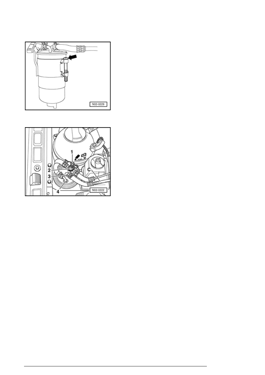
- Install the filter and secure with screw - arrow - 

- Install regulator valve - 2 - and the retaining clip - 1 - 

- Install the fuel lines to the hose connections - 3 - and - 4 - 
and secure hoses with hose clamps. 

- Start the engine and perform a visual inspection of the 
fuel system for leaks. 

- Rev the engine several times. Thereafter, the fuel must 
flow through the see-through line - C - without any bubbles 
while at idle. 

Fuel filter, draining (diesel engine)


Note: 

Make sure that no diesel fuel gets onto the coolant hoses. 
If necessary, clean hoses immediately!  
 
Observe waste disposal regulations!  


Perform the following work sequence:

Description of work (part 2 of 2)

13/2/2005


- Remove the retaining clip - 1 - and remove regulator valve 
- 2 - with attached fuel lines. 

- Place a hose onto the hose connection of the drain screw 
- arrow - , open the screw, and drain approx. 0.1 L of fluid. 

- Tighten the drain screw - arrow - and remove the hose. 

- Install a new O-ring for the sealing of the regulating valve.  

- Install regulator valve - 2 - and the retaining clip - 1 - 

- Start the engine and perform a visual inspection of the 
fuel system for leaks. 

- Rev the engine several times. Thereafter, the fuel must 

Description of work (part 2 of 2)

13/2/2005


flow through the see-through line - C - without any bubbles 
while at idle. 

Automatic transmission, check ATF level


Perform the following work procedure 


 Repair Manual, Automatic transmission, Repair Group 

39, ATF level, checking and filling 

Power assisted steering, check oil level


Perform the following work sequence:

Oil, when cold


- With engine not running, move front wheels in straight-
ahead position. 

- Insert a suitable screwdriver into the recess at the cap  
arrow - 
and unscrew caps with dipstick. 

- Clean dipstick with clean cloth. 

- Screw cap on hand-tight and remove again. 

Note: 

Screw cap fully in to get an accurate fluid level reading.   
 

Description of work (part 2 of 2)

13/2/2005


- Check oil level: The oil level must be in the range of the 
indicated field - A - 

Note: 

If fluid level is above the mark, some fluid must be 
extracted.  
 
If the fluid level is below the specified level, check the 
hydraulic system for leaks (repair measure). It is not 
enough to simply top off with oil. If no leaks are detected, 
top off with hydraulic fluid "G 002 000" .   
 

- Screw cap on hand-tight (with screwdriver). 

Hydraulic fluid at operating temperature (from 
approx. 122   F (50   C)): 

- With engine not running, move front wheels in straight-
ahead position. 

- Insert a suitable screwdriver into the recess at the cap  
arrow - 
and unscrew caps with dipstick. 

- Clean dipstick with clean cloth. 

- Screw cap on hand-tight and remove again. 

Description of work (part 2 of 2)

13/2/2005


Content   ..  1232  1233  1234  1235   ..