Volkswagen Fox (2004 year). Manual - part 29
 

  Index      Volkswagen     Volkswagen Fox - service repair manual 2004 year


Search            copyright infringement  


Content   ..  27  28  29  30   ..


Volkswagen Fox (2004 year). Manual - part 29


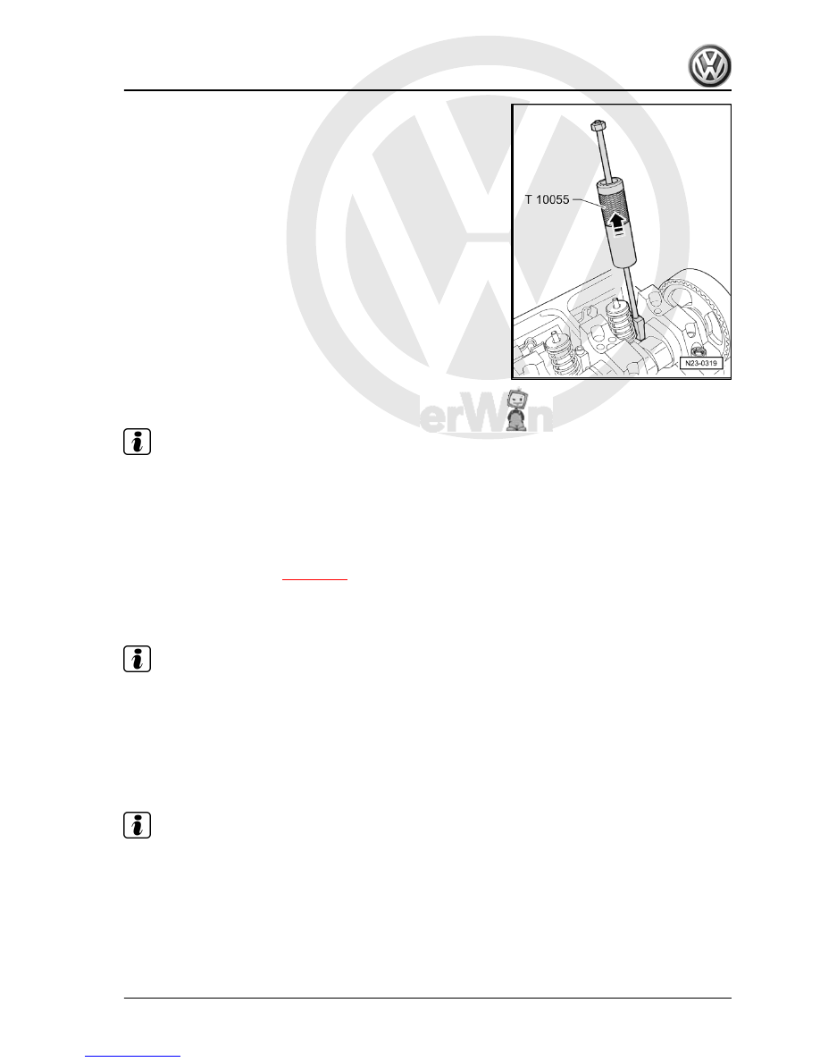
– Pull the injector out of cylinder head seat with gentle taps.

1.7.2

Installation

Note

♦

After each repair, the injector requires adjustment, and the

rocker arm set screw and the injector ball head pin need to be

replaced.

♦

The new injectors are supplied with rings and heat insulation

cover.

– The heat insulation cover and rings must be replaced when

the old injector is reused 

⇒ page 109

– Check whether the three rings and the heat insulation cover,

together with the fastening clip, are correctly seated before

installing the injector.

Note

The rings cannot not be twisted.

– Lubricate the rings and carefully set the injector into the cylin‐

der head.

– In a uniform manner push the injector into the cylinder head

until it stops.

– Fit the tensioning block into the slot at the injector side.

Note

If the injector is not at a right angle to the tensioning block, the

fastening screw may come loose, thus damaging the injector or

the cylinder head.

– Align the injector as follows.
– Tighten the new securing bolt into the tensioning block until

the injector can still be turned easily.

– Align the injector at a right angle to the camshaft bearing caps.

Fox 2004 ➤

1. Maintaining the direct injection Diesel system    

113


(measurement range at least of 400 mm).

Cylinder

Dimension “a”

1

245.0 ± 0.8 mm

2

157.0 ± 0.8 mm

3

65.6 ± 0.8 mm

– Align the injector and tighten the securing bolt to: 12 Nm + 270°

(the angular torque could be made in several stages).

– Fit the rocker arm shaft and tighten the new securing bolts as

follows

– Tighten the inner and then both outer bolts manually and

evenly. Next, by using the same sequence, tighten to 20 Nm

+ 90°.

– Fit the Bracket -VW 387- onto the set screw as shown.
– Turn crankshaft in the engine rotation direction until rocker arm

roller is at the top of drive cam. Roller side -arrow A- positioned

at the highest point of dial gauge -arrow B- positioned at the

lowest point.

– Remove dial gauge.
– Turn set screw inwards into rocker arm until a firm resistance

is noted (injector positioned at stop).

– Turn set screw 225° back off stop.
– Hold set screw in this position and tighten the self-locking nut

to 30 Nm.

– Fit injector connector and install cylinder head cover and tim‐

ing belt guard.

Fox 2004 ➤

114


2.1

Engine command unit - remove and in‐

stall

– Before removing engine command unit, refer to the command

unit ID and this respective code 

⇒ page 115

 .

2.1.1

Removal

– Switch off ignition.
– Remove the windscreen wiper blades and the lower coating

of the windscreen frame.

– Release the connector on the engine command unit and pull

it off.

– Push clips -arrows- outwards and pull command unit out.

2.1.2

Installing

– Insert new command unit.
– Fit connector and lock in position.
– Check the previous code and encode the new command unit

⇒ page 116

 .

2.2

Querying and erasing fault memory of

the engine command unit

Special tools and workshop equipment required
♦ Diagnosis, Measurement and Information System -VAS

5051A/52-

♦ Diagnosis cable (3 m) -VAS 5051/1- or Diagnosis cable (5 m)

-VAS 5051/3-

Fox 2004 ➤

2. Engine command unit    

115


– Connect Diagnosis cable (3 m) -VAS 5051/1- or Diagnosis

cable (5 m) -VAS 5051/3- to the diagnosis connection.

– Start the engine and run it at idle speed.
Only when engine does not run:
– Switch ignition on.
Select operation mode
– Press on the 

Vehicle self-diagnosis

.

Select vehicle system
– Press on the 

01 Engine electronic system

.

The command unit ID and the code will be indicated on the dis‐

play.
Select diagnosis function:
– Press on the 

02 Query fault memory 

 on the display.

– If no faults are stored in engine command unit, the display

shows “0 faults found”.

– If there are faults stored in the engine command unit, they will

appear sequentially on the display.

– Press 

←

 key.

– Press on the 

05 Erase fault memory 

 on the display.

– Press 

06 End the test

 function key.

2.3

Adjusting functions and components

Special tools and workshop equipment required
♦ Diagnosis, Measurement and Information System -VAS

5051A/52-

♦ Diagnosis cable (3 m) -VAS 5051/1- or Diagnosis cable (5 m)

-VAS 5051/3-

Select, in the Diagnosis, Measurement and Information System -

VAS 5051A/52- the “Assisted fault finding”.
After querying all the command units:
– Press 

Skip

 key.

– Select 

Function/component selection

.

– Select 

Activation

.

– Select 

engine identification codes

.

Fox 2004 ➤

116


Content   ..  27  28  29  30   ..