Volkswagen Fox (2004 year). Manual - part 13
 

  Index      Volkswagen     Volkswagen Fox - service repair manual 2004 year


Search            copyright infringement  


Content   ..  11  12  13  14   ..


Volkswagen Fox (2004 year). Manual - part 13


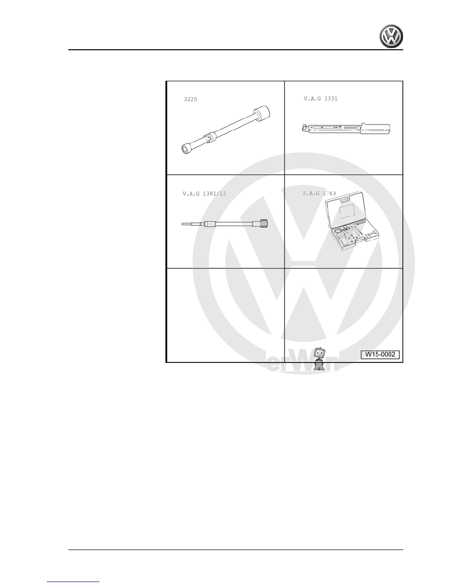
Special tools and workshop

equipment required
♦ U/J extension and socket,

10 mm -3220-

♦ Torque wrench - 5 to 50 Nm

(enc. 1/2") -VAG 1331-

♦ Adapter -V.A.G 1381/12-
♦ Compression meter -

V.A.G 1763-

Test conditions
• Minimum engine oil temperature 30 °C.
Test sequence
– Remove central connector from unit injectors.
– Remove all glow plugs, using U/J extension and socket, 10

mm -3220- .

Fox 2004 ➤

1. Cylinder head - remove and install    

49


Note

How to use the compression meter ⇒  Instruction Manual .

– Operate the starter motor until the meter does not indicate fur‐

ther increase in pressure.

Compression pressure:
New: 25...31 bar. Wear limit: 19 bar.
Permissible difference between all cylinders: 5 bar.
– Install glow plugs with U/J extension and socket, 10 mm

-3220- . Tightening torque: 15 Nm.

– Check fault memory, eliminate possible present failures and,

then, erase fault memory 

⇒ page 115

 .

Note

Removing the central connector from unit injectors causes faults

to be recorded. Therefore, check the fault memory and erase it,

when required.

Fox 2004 ➤

50


Note

♦

Cylinder heads with cracks between the valve seats can still

be used without reducing their useful life when such cracks

are small, maximum 0.5 mm wide.

♦

All bearing and running surfaces must be lubricated before in‐

stalling.

WARNING

Always replace self-locking nuts and screws subject to angular

torque

1 - 20 Nm + 90°

❑ Replace after each re‐

moval.

❑ Loosen and tighten in

the proper order

⇒ page 58

2 - Injector drive arm shaft
3 - Cylinder head securing bolt

❑ Replace.
❑ Loosen and tighten in

the proper order

⇒ page 46

❑ Before installing, set

washers in cylinder

head.

4 - Washer

❑ For head screws.

5 - Tappet

❑ Do not interchange.
❑ With hydraulic offsetting

of valve gap.

❑ Store with cam lobe

contact surface down‐

wards.

❑ Check camshaft axial

clearance before instal‐

ling 

⇒ page 52

❑ Lubricate contact sur‐

face.

❑ Before removing, re‐

move the camshaft

bearing caps.

6 - Keys
7 - Valve spring upper plate
8 - Valve spring

❑ Removing and installing: Cylinder head removed: with Compressor device -2037- mounted

⇒ page 56

 .

Fox 2004 ➤

2. Valve command - repair    

51


⇒ page 56

 .

❑ Install in the cylinder head before putting the bearing caps.

10 - Valve stem seal

❑ Replace 

⇒ page 56

 .

11 - Valve guide

❑ Check 

⇒ page 55

 .

12 - Injection unit

❑ Remove and install 

⇒ page 112

 .

13 - Cylinder head

❑ See note 

⇒ page 51

 .

❑ Rework valve seats 

⇒ page 53

14 - Oil seal

❑ Do not apply additional lubricant or grease to the seal lip.
❑ Before installation, remove oil residues from crankshaft trunnion with clean cloth.
❑ For installation, cover the groove in the camshaft tapered section with adhesive tape.
❑ Remove and install.

15 - Valves

❑ Valve dimensions 

⇒ page 53

16 - Bearing shell

❑ Do not interchange used bearing shells (mark)
❑ Ensure proper seating of retaining clips in bearing caps and cylinder head.

17 - Camshaft

❑ Check axial clearance 

⇒ page 52

❑ Remove and install 

⇒ page 58

 .

❑ Check radial clearance with Plastigage. Wear limit: 0.11 mm.
❑ Excentricity: max. 0.01 mm.
❑ Valve identification and synchronization 

⇒ page 53

18 - Bearing cap

❑ Installation sequence 

⇒ page 58

 .

❑ Bearing cap 4 is identified as bearing cap 5.
❑ When installing, use Sealant -AMV 17400401- to seal surfaces of bearing caps 1 and 4, which contact

cylinder head

19 - 8 Nm + 90°

❑ Replace after each removal .

Check camshaft axial clearance

Fox 2004 ➤

52


Content   ..  11  12  13  14   ..