Volkswagen Fox (2004 year). Manual - part 7
 

  Index      Volkswagen     Volkswagen Fox - service repair manual 2004 year


Search            copyright infringement  


Content   ..  5  6  7  8   ..


Volkswagen Fox (2004 year). Manual - part 7


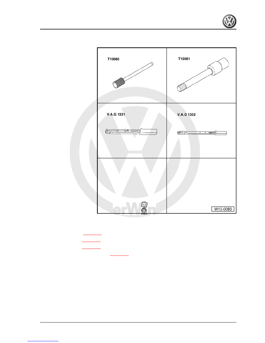
Special tools and workshop

equipment required
♦ Pin -T10060-
♦ Multi-point spanner -

T10061-

♦ Torque wrench - 5 to 50 Nm

(enc. 1/2") -VAG 1331-

♦ Torque wrench - 40 to 200

Nm (enc. 1/2") -VAG 1332-

♦ Spanner (24/27 mm AF)

3.1.1

Removal

– Remove Poly-V belt 

⇒ page 14

 .

– Remove timing belt 

⇒ page 41

 .

– Remove crankcase 

⇒ page 68

 .

– Remove sealing flange, pulley side 

⇒ page 17

 .

– Remove cover securing bolts.
– Remove cover from mounting frame.

Fox 2004 ➤

3. Counterbalance shaft and retaining frame - remove and install    

25


– Loosen the gear -1- from mounting frame.
– Remove securing bolt --2-- from chain tensioning element and

remove it.

– Remove the chain and put it on a clean surface.

– Immobilise counterbalance shaft, as shown, with a Spanner

(24/27 mm AF) -1-.

Note

When immobilizing the counterbalance shaft, make sure that the

spanner is centred on the counterbalance and at right angles to

counterbalance shaft.

– Loosen fastening bolt -2- of the counterbalance.

Note

Only loosen the fastening bolt -2- of the counterbalance; do not

remove.

– Unbolt mounting frame --3-- from engine block and remove it

with counterbalance shaft.

– Put the mounting frame on a clean surface.
– Remove counterbalance securing bolts.
– Remove counterbalance and counterbalance shaft gear.
– Turn the counterbalance shaft so that it can be removed from

the bearing.

3.1.2

Installing

– Sliding surfaces of the bearing oil.
– Set counterbalance shaft in bearing.
– Fit the gear and counterbalance on counterbalance shaft.

Note

Installing the gear and counterbalance is only possible in a single

position.

– Hand tighten securing bolt for counterbalance weight and

gear.

– Tighten mounting frame to engine block by hand so that there

is no play.

Fox 2004 ➤

26


When positioning the frame, make sure that the fastening

guide is inserted into the engine block and the O-ring is fitted

in the mounting frame.

♦

Align the mounting frame so that it fits flush with the outer edge

of the engine block on the pulley end.

– Bolt mounting frame with counterbalance shaft to engine

block. Tightening torque: 20 Nm.

– Check that mounting frame aligns flush with outer edge of en‐

gine block on the pulley end.

– Immobilise counterbalance shaft, as shown, with a Spanner

(24/27 mm AF) -1-.

Note

When immobilizing the counterbalance shaft, make sure that the

spanner is centred on the counterbalance and at right angles to

counterbalance shaft.

– Tighten fastening bolt -2- of the counterbalance. Tightening

torque: 100 Nm +90°.

Note

The fastening bolt is a tensioning bolt and must always be re‐

placed.

– Install chain tensioning element. Tightening torque: 8 Nm +

90°.

Note

The fastening bolts of the chain tensioning element are tensioning

bolts and must always be replaced.

– Clean chain with a lint-free cloth.

– Ensure that mark on crankshaft sprocket -arrow- is at top.

Fox 2004 ➤

3. Counterbalance shaft and retaining frame - remove and install    

27


the crankshaft sprocket and counterbalance sprocket align

with the colour-coded chain links -arrows-.

Note

The colour-coded chain links are marked with a notch.

– Fit the free sprocket in the chain and tighten the free sprocket

to the mounting frame. Tightening torque: 20 Nm.

– Remove Locking pin -T10060- from chain tensioning element.

– Make sure that the marks on the crankshaft sprocket and

counterbalance shaft sprocket align with the colour-coded

chain links -arrows-.

Note

The colour-coded chain links are marked with a notch.

– Install pulley end sealing flange 

⇒ page 17

 .

– Install counterbalance shaft cover. Tightening torque: 5 Nm.

Note

♦

Before installing cover, lubricate O-ring of oil pump, as well as

shaft on inside of cover

♦

Make sure of the proper seating of sealing strip in cover.

♦

When installing cover, ensure that cover engages in mounting

frame.

– Install crankcase 

⇒ page 68

 .

– Install and adjust timing belt 

⇒ page 41

 .

– Install Poly-V belt 

⇒ page 14

 .

Fox 2004 ➤

28


Content   ..  5  6  7  8   ..