Toyota Corolla (2020 year). Owner's manual - part 15
230
4-5. Using the driving support systems
When constant speed control
mode is selected, your vehicle
will maintain a set speed without
controlling the vehicle-to-vehi-
cle distance. Select this mode
only when vehicle-to-vehicle dis-
tance control mode does not
function correctly due to a dirty
radar, etc.
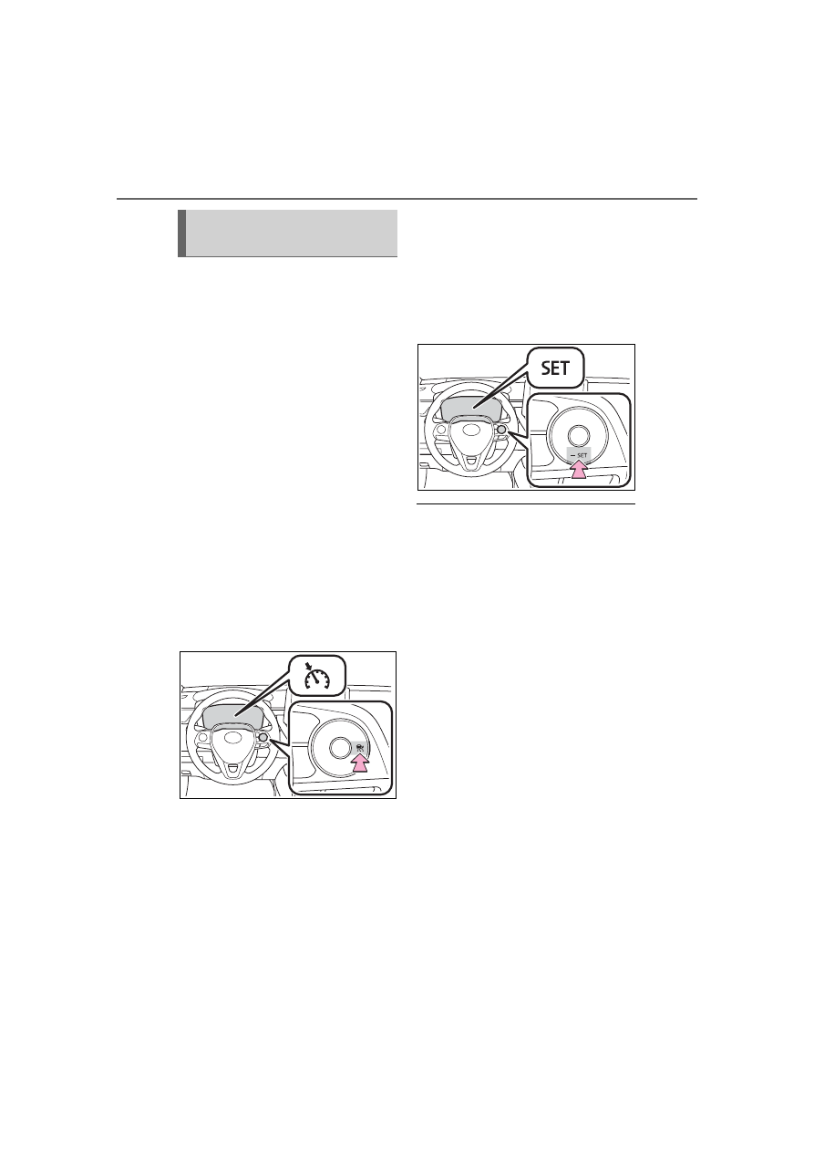
1
With the cruise control off,
press and hold the cruise
control main switch for 1.5
seconds or more.
Immediately after the switch is
pressed, the dynamic radar cruise
control indicator will come on. After-
wards, it switches to the cruise con-
trol indicator.
Switching to constant speed control
mode is only possible when operat-
ing the switch with the cruise con-
trol off.
2
Accelerate or decelerate,
with accelerator pedal opera-
tion, to the desired vehicle
speed (at or above approxi-
mately 20 mph [30 km/h])
and press the “-SET” switch
to set the speed.
Cruise control “SET” indicator will
come on.
The vehicle speed at the moment
the switch is released becomes the
set speed.
Adjusting the speed setting:
P.227
Canceling and resuming the speed
setting: P.229
■
Dynamic radar cruise control
can be set when
●
Vehicles with a continuously vari-
able transmission: The shift lever
is in D.
●
Vehicles with a manual transmis-
sion: The shift lever is in range
2nd or higher.
●
Depending on the control mode,
this item can be set at the follow-
ing speeds.
• Vehicle-to-vehicle distance con-
trol mode: Approximately 20 mph
(30 km/h) or more
• Constant speed control mode:
Approximately 20 mph (30 km/h)
or more
■
Accelerating after setting the
vehicle speed
The vehicle can accelerate by oper-
ating the accelerator pedal. After
accelerating, the set speed
resumes. However, during vehi-
cle-to-vehicle distance control
mode, the vehicle speed may
decrease below the set speed in
order to maintain the distance to the
preceding vehicle.
Selecting constant speed
control mode