Toyota Automatic Transmission A340 Series. Repair Manual - part 34


  Index      Toyota     Toyota Automatic Transmission A340 Series. Repair Manual


Search            copyright infringement  


Content   ..  32  33  34  35   ..


Toyota Automatic Transmission A340 Series. Repair Manual - part 34


AT4846

AT7910

AT4940

mm (in.)

23 (0.91)

12 (0.47)

20

(0.79)

AT1354

AT5066

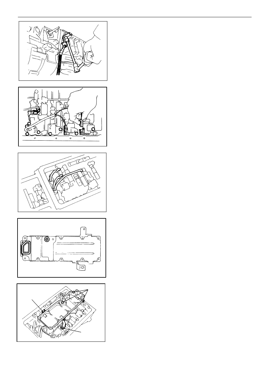
53. INSTALL TRANSMISSION SOLENOID WIRING

(a)

Coat a new O−ring with ATF and install it to the

grommet.

(b)

Insert the solenoid wiring to the case and install

the stopper plate.

(c)

Connect the connectors to No. 1, No. 2 and lock−

up solenoids.

54. INSTALL OIL TUBES

Using a plastic hammer, install the three tubes into

position shown in the figure.

NOTICE: Be careful not to bend or damage the tubes.

55. INSTALL OIL STRAINER AND GASKETS

(a)

Install two new gaskets to the oil strainer case.

(b)

Install the oil strainer case and torque the five bolts.

Torque: 100 kg−cm (7 ft−lb, 10 N−m)

HINT: Each bolt length (mm, in.) is indicated in the figure.

AUTOMATIC TRANSMISSION (A340H)

Installation of Component Parts

AT−261

AT4908

mm (in.)

AT4942

20 (0.78)

60

(2.34)

30

(1.17)

25 (0.98) 25 (0.98)

30 (1.17)

AT4907

w/ A.D.D.

AT2941

AT8028

(c)

Install a new gasket to the oil strainer case.

(d)

Install the oil strainer and torque the eleven bolts.

Torque: 70 kg−cm (61 in.−lb, 6.9 N−m)

56. INSTALL PARKING LOCK PAWL BRACKET

Torque: 70 kg−cm (61 in.−lb, 6.9 N−m)

57. INSTALL TRANSFER SOLENOID WIRING

(a)

Coat a new O−ring with ATF and install it to the

grommet.

(b)

Install solenoid wiring into the transfer case.

(c)

Install the stopper plate.

58. INSTALL TRANSFER VALVE BODY

(a)

Align the groove of the manual valve to the pin of

the lever.

(b)

Install and torque the six bolts.

Torque: 100 kg−cm (7 ft−lb, 10 N−m)

HINT: Each bolt length (mm, in.) is indicated in the fig-

ure.

(c)

Connect the connectors to No. 4 solenoid and

transfer pressure switch.

(d)

Clamp the wiring.

AT−262

AUTOMATIC TRANSMISSION (A340H)

Installation of Component Parts

AT7912

2 − 3 mm (0.08 − 0.12 in.)

AT7940

Apply

Sealant

AT7909

mm (in.)

246 (9.69)

(2.83)

82 (3.23)

72

30 (1.18) − 67 (2.64)

10 (0.39)

5 (0.20)

52 (2.05)

10 (0.39)

30 (1.18)

AT1362

2 − 3 mm (0.08−0.12 in.)

AT5065

mm (in.)

91 (3.58)

46

(1.81)

97

(3.82)

(2.28)

58

(3.27)

83

59. INSTALL TRANSFER OIL PAN

(a)

Install the three magnets as shown in the figure.

(b)

Remove any packing material and be careful not to

drop the oil on the contacting surfaces of the oil pan

and transfer case.

(c)

Apply seal packing to the oil pan as shown in the

figure.

Seal packing:  Part No. 08826 − 00090, THREE

BOND 1281 or equivalent

(d)

Apply sealant to the threads of the three bolts.

Sealant: 

Part No. 08833 − 00070, THREE BOND

1324 or equivalent

(e)

Install the oil pan and torque the eleven bolts.

Torque: 75 kg−cm (65 in.−lb, 7.4 N−m)

60. INSTALL TRANSMISSION OIL PAN

(a)

Install the six magnets as shown in the figure.

(b)

Remove any packing material and be careful not

to drop oil on the contacting surfaces of the trans-

mission case and oil pan.

(c)

Apply seal packing to the oil pan as shown in the

figure.

Seal packing:  Part No. 08826 − 00090, THREE

BOND 1281 or equivalent

AUTOMATIC TRANSMISSION (A340H)

Installation of Component Parts

AT−263

AT7939

E7051

E7264

E7265

”H4” Position

E7058

(d)

Install and torque the nineteen bolts.

Torque: 75 kg−cm (65 in.−lb, 7.4 N−m)

61. INSTALL TRANSMISSION HOUSING

Install and torque the six bolts.

Torque: 

10 mm bolt  345 kg−cm (25 ft−lb, 34 N−m)

12 mm bolt  580 kg−cm (42 ft−lb, 57 N−m)

62. INSTALL SPEED SENSOR

(a)

Coat a new O−ring with ATF and install it to the

speed sensor.

(b)

Install the speed sensor and stopper plate.

(c)

Connect the wiring connector.

63. INSTALL TRANSFER POSITION SWITCH

(a)

Install the transfer position switch onto the manu-

al valve lever shaft and temporarily tighten the

adjusting bolt.

(b)

Install the grommet and a new lock washer. Install

and torque the nut.

Torque: 40 kg−cm (35 in.−lb, 3.9 N−m)

(c)

Using the control shaft lever, shift the lever into the

”H4” position.

AT−264

AUTOMATIC TRANSMISSION (A340H)

Installation of Component Parts

AT8390

AT7968

AT4230

AT4943

AT4503

Switch

Groove

Basic

Line

(d)

Align the basic line and the switch groove, and

tighten the bolt.

Torque: 130 kg−cm (9 ft−lb, 13 N−m)
(e)

Bend the tabs of the lock washer.

HINT: Bend at least two of the lock washer tabs.

64. INSTALL TRANSFER CONTROL SHAFT LEVER

Torque: 160 kg−cm (12 ft−lb, 16 N−m)

65. INSTALL SPEEDOMETER DRIVEN GEAR

(a)

Coat a new O−ring with ATF and install it to the

sleeve.

(b)

Install the driven gear into the sleeve and install

the clip.

(c)

Install the sleeve to the extension housing.

(d)

Install the lock plate with the bolt.

(e)

Torque the bolt.

Torque: 160 kg−cm (12 ft−lb, 16 N−m)

66. INSTALL TRANSFER SIDE UNIONS

(a)

Coat new two O−rings with ATF and install them

to each union.

(b)

Install the outlet union as shown in the figure.

Torque: 300 kg−cm (22 ft−lb, 29 N−m)

(c)

Install the inlet union as shown in the figure.

Torque: 300 kg−cm (22 ft−lb, 29 N−m)

AUTOMATIC TRANSMISSION (A340H)

Installation of Component Parts

AT−265

AT8380

AT4844

AT7916

AT4944

E7270

67. INSTALL TRANSFER OIL COOLER TUBES

(a)

Install the tube clamp bracket.

Torque: 345 kg−cm (25 ft−lb, 34 N−m)
(b)

Install the outlet tube.

Torque: 350 kg−cm (25 ft−lb, 34 N−m)

(c)

Install the inlet tube.

Torque: 350 kg−cm (25 ft−lb, 34 N−m)
(d)

Install the tube clamp.

Torque: 100 kg−cm (7 ft−lb, 10 N−m)

68. INSTALL TRANSMISSION AND TRANSFER FLUID

TEMPERATURE SENSORS
(a)

Coat new O−rings with ATF and install them to

each sensor.

(b)

Install and torque the transmission and transfer

fluid temperature sensors.

Torque: 150 kg−cm (11 ft−lb, 15 N−m)

69. INSTALL TRANSMISSION SIDE UNIONS

(a)

Coat new two O−rings with ATF and install them

to each union.

(b)

Install the front union as shown in the figure.

Torque: 300 kg−cm (22 ft−lb, 29 N−m)

AT−266

AUTOMATIC TRANSMISSION (A340H)

Installation of Component Parts

AT4505

E7275

Neutral

Position

AT4369

Groove

Neutral

Basic Line

AT4504

AT7969

(c)

Install the rear union as shown in the figure.

Torque: 300 kg−cm (22 ft−lb, 29 N−m)

70. INSTALL NEUTRAL START SWITCH

(a)

Install the neutral start switch onto the manual

valve lever shaft and temporarily tighten the ad-

justing bolt.

(b)

Install the grommet and a new lock washer. Install

and torque the nut.

Torque: 70 kg−cm (61 in.−lb, 6.9 N−m)

(c)

Using the control shaft lever, fully turn the manual

lever shaft back and return two notches. It is now

in neutral.

(d)

Align the neutral basic line and the switch groove,

and tighten the adjusting bolt.

Torque: 130 kg−cm (9 ft−lb, 13 N−m)
(e)

Bend the tabs of the lock washer.

HINT: Bend at least two of the lock washer tabs.

71. INSTALL TRANSMISSION CONTROL SHAFT LEVER

Torque: 160 kg−cm (12 ft−lb, 16 N−m)

AUTOMATIC TRANSMISSION (A340H)

Installation of Component Parts

AT−267

AT4625

E7040

72. INSTALL WIRE HARNESS CLAMPS

AT−268

AUTOMATIC TRANSMISSION (A340H)

Installation of Component Parts


Content   ..  32  33  34  35   ..