Toyota Automatic Transmission A340 Series. Repair Manual - part 2
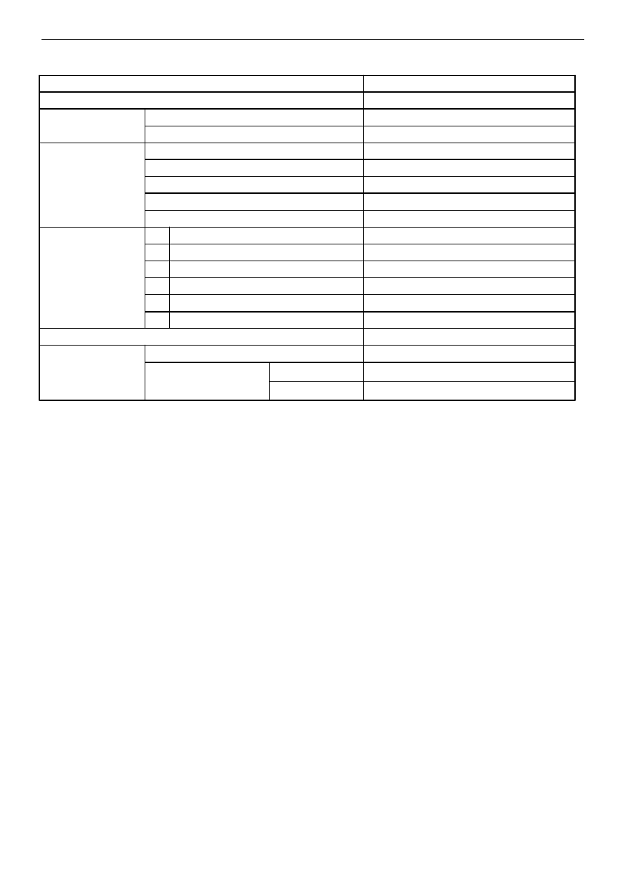
Type of Transmission
A340E
Type of Engine
7M−GE, 7M−GTE, 3VZ−E
Torque Converter
Stall Torque Ratio
Truck : C & C 2.0 : 1 Others 2.1 : 1
Lock−Up Mechanism
Equipped
Gear Ratio
1st Gear
2.804
2nd Gear
1.531
3rd Gear
1.000
O/D Gear
0.705
Reverse Gear
2.393
Plates (Disc/Plate)
C
0
O/D Direct Clutch
2/2
C
1
Forward Clutch
5/5
C
2
Direct Clutch
4/4
B
2
2nd Brake
5/5
B
3
1st & Reverse Brake
6/6
B
0
O/D Brake
4/3
mm (in.)
Second Coast Brake Band Width
40 (1.57)
ATF
Type
ATF DEXRONR II
Capacity
liters (US qts, Imp. qts)
Total
7.2 (7.6, 6.3)
Drain and Refill
1.6 (1.7, 1.4)
General Specifications
−
AUTOMATIC TRANSMISSION
Description
AT−5