Toyota FJ Cruiser (GSJ 10, 15 series). Instruction - part 347
PM–12
PARK ASSIST / MONITORING – CLEARANCE SONAR SYSTEM
PM
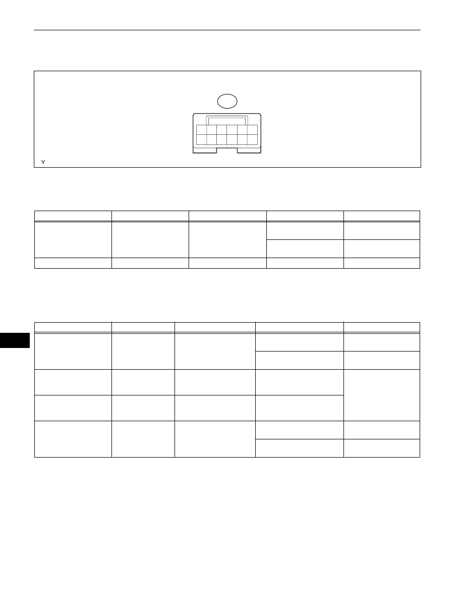
TERMINALS OF ECU
1.
CLEARANCE WARNING ECU
(a) Disconnect the E31 ECU connector.
(b) Measure the voltage of the wire harness side
connector.
Standard voltage:
If the result is not as specified, there may be a
malfunction on the wire harness side.
(c) Reconnect the ECU connector.
(d) Measure the voltage of the connector.
Standard voltage:
If the result is not as specified, the ECU may have a
malfunction.
1
2
3
4
5
6
7
8
9
10
11
12
E31
I102375E02
Symbols (Terminal No.)
Wiring Color
Terminal Description
Condition
Specified Condition
+B (E31-3) - Body ground
LG - Body ground
+B power supply
Ignition switch ON, back
sonar switch ON
11 to 14 V
Ignition switch ON, back
sonar switch OFF
Below 1 V
E (E31-10) - Body ground
W-B - Body ground
Body ground
Always
Below 1 V
Symbols (Terminal No.)
Wiring Color
Terminal Description
Condition
Specified Condition
BBZ (E31-2) - E (E 31-10)
L-B - W-B
Buzzer input
Ignition switch ON, back sonar
switch ON
Pulse generation
Ignition switch ON, back sonar
switch OFF
Below 1 V
S6 (E31-12) - E1 (E31-11)
P - Y
No. 1 ultrasonic sensor
(LH)
When signal transmitted from
ECU to No. 1 ultrasonic
sensor (LH)
Pulse generation
S5 (E31-6) - E2 (E31-5)
B - W
No. 1 ultrasonic sensor
(RH)
When signal transmitted from
ECU to No. 1 ultrasonic
sensor (RH)
RL (E31-8) - Body ground
R-Y - Body ground
Back-up light switch signal
input
Ignition switch ON, shift lever
in reverse position
11 to 14 V
Ignition switch ON, shift lever
except reverse position
Below 1 V