Toyota FJ Cruiser (GSJ 10, 15 series). Instruction - part 322


  Index      Toyota     Toyota FJ Cruiser (model GSJ 10, 15 series) - service repair instruction 2007 year


Search            copyright infringement  


Content   ..  320  321  322  323   ..


Toyota FJ Cruiser (GSJ 10, 15 series). Instruction - part 322


ME–20

METER  –  METER / GAUGE SYSTEM

ME

*: for M/T

ACCESSORY METER ASSEMBLY

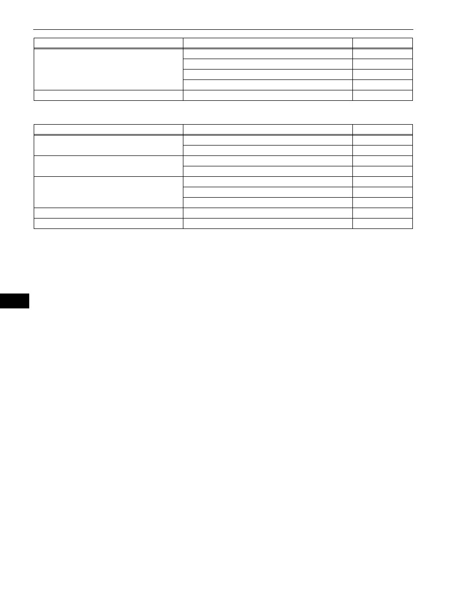
Key reminder warning buzzer does not sound

Unlock warning switch assembly

DL-102

Main body ECU

ME-17

Wire harness or connector

-

Combination meter assembly

ME-17

Manual shift reverse warning does not sound*

Combination Meter Assembly

ME-17

Symptom

Suspected area

See page

Symptom

Suspected area

See page

Illumination does not come on

Wire harness or connector

-

Accessory meter assembly

-

Accessory meter does not operate

Wire harness or connector

-

Accessory meter assembly

-

Ambient temperature does not display

Air conditioning amplifier

AC-5

Wire harness or connector

-

Accessory meter assembly

-

Compass does not operate

Accessory meter assembly

-

Clinometer does not operate

Accessory meter assembly

-

METER  –  METER / GAUGE SYSTEM

ME–21

ME

TERMINALS OF ECU

1.

COMBINATION METER ASSEMBLY

(a) Disconnect the E13 combination meter assembly 

connector.

(b) Measure the voltage and resistance of the wire 

harness side connector.

Standard:

If the result is not as specified, there may be a 
malfunction in the wire harness.

(c) Disconnect the E14 combination meter assembly 

connector.

(d) Measure the voltage of the wire harness side 

connector.

Standard voltage:

E14

E13

E125398E01

Symbols (Terminals No.)

Wiring Color

Terminal Description

Condition

Specified Condition

IG+ (E13-2) - Body ground

R-L - Body ground

Ignition switch signal

Ignition switch OFF 

→ ON

Below 1 V 

→ 11 to 14 V

B (E13-1) - Body ground

R - Body ground

Battery

Always

11 to 14 V

ES (E13-21) - Body 

ground

W-B - Body ground

Ground

Always

Below 1 

Symbols (Terminals No.)

Wiring Color

Terminal Description

Condition

Specified Condition

SE *1 (E13-4) - Body 

ground

W - Body ground

Vehicle speed signal 

(Output)

Driving at approx. 12 mph 

(20 km/h)

Pulse generation

(See waveform 2)

E3 (E13-5) - Body ground

Y-B - Body ground

Fuel level signal

Ignition switch ON

11 to 14 V

SW (E13-6) - Body ground

B-Y - Body ground

Airbag signal

Airbag warning light ON 

→ 

OFF

Below 1 V 

→ 11 to 14 V

WRNP (E13-7) - Body 

ground

LG - Body ground

Passenger side seat belt 

warning light signal 

(Output)

Ignition switch ON

Front passenger seat is 

occupied and its seat belt 

is unfastened

11 to 14 V 

→ Below 1 V

Ignition switch ON

Front passenger seat is 

occupied and its seat belt 

is fastened

Below 1 V 

L (E13-8) - Body ground

G-Y - Body ground

Seat belt condition signal 

(Driver side)

D-BELT indicator light ON

Below 1 V

D-BELT indicator light 

OFF

11 to 14 V

KSW (E13-9) - Body 

ground

V-G - Body ground

Key switch condition 

signal

Key inserted

Below 1 V

Key removed

11 to 14 V

PBKL (E13-10) - Body 

ground

L-R - Body ground

Front seat inner belt signal 

(Front passenger side)

Ignition switch ON

Front seat belt is 

unfastened or fastened 

(Front passenger side)

Pulse generation

ILL- (E13-11) - Body 

ground

BR-W - Body ground

Light control rheostat 

signal

Ignition switch OFF 

→ ON

Pulse generation

(See waveform 1)

ME–22

METER  –  METER / GAUGE SYSTEM

ME

S (E13-12) - Body ground

B-W - Body ground

Tachometer signal

Idling

Pulse generation

(See waveform 2)

SI (E13-13) - Body ground

R-Y*1 - Body ground

Vehicle speed signal 

(Input)

Driving at approx. 12 mph 

(20 km/h)

Pulse generation

(See waveform 2)

GR-R*2 - Body ground

+S (E13-14) - Body 

ground

V-R - Body ground

Vehicle Speed signal 

(Input)

Ignition switch ON and 

wheel turning slowly

Pulse generation

(See waveform 2)

TEMP (E13-15) - Body 

ground

BR-B - Body ground

Engine coolant 

temperature

Ignition switch ON

Engine coolant 

temperature 90

°C(194°F)

Pulse generation

(See waveform 3)

L (E13-16) - Body ground

V-W - Body ground

Fuel level signal

Ignition switch ON

11 to 14 V

ESC (E13-17) - Body 

ground

LG-R - Body ground

ABS signal

ABS warning light ON 

→ 

OFF

Below 1 V 

→ 11 to 14 V

B (E13-18) - Body ground

P - Body ground

Turn signal RH signal

Ignition switch ON

Turn signal RH indicator 
light OFF 

→ ON → OFF

Below 1 V 

→ 11 to 14 V → 

Below 1 V

B (E13-20) - Body ground

L-W - Body ground

Turn signal LH signal

Ignition switch ON

 Turn signal LH indicator 

light OFF 

→ ON → OFF

Below 1 V 

→ 11 to 14 V → 

Below 1 V

SW (E13-23) - Body 

ground

V-Y - Body ground

All door condition signal

All doors open 

→ closed

Below 1 V 

→ 11 to 14 V

+ (E13-26) - Body ground

R-W - Body ground

HEAD light signal

Light control switch OFF 

→ ON

Below 1 V 

→ 11 to 14 V

DOOR (E13-29) - Body 

ground

 W-L - Body ground

Driver side door open

Driver side door open 

→ 

closed

Below 1 V 

→ 11 to 14 V

PKB (E13-31) - Body 

ground

B-L - Body ground

Brake fluid level warning 

light signal

Ignition switch ON

Brake fluid level warning 

light ON 

→ OFF

Below 1 V 

→ 11 to 14 V

PRSW*8 (E14-1) - Body 

ground

L-Y - Body ground

Rear differential lock 

signal

Rear differential lock 

warning light ON 

→ OFF

Below 1 V 

→ 11 to 14 V

SW*4 (E14-2) - Body 

ground

R-L*3 - Body ground

4WD signal

4WD indicator OFF 

→ ON

Below 1 V 

→ 11 to 14 V

GR*1 - Body ground

CHG- (E14-3) - Body 

ground

GR - Body ground

Change signal

Ignition switch ON 

→ OFF

11 to 14 V 

→ Below 1 V

A/D*6 (E14-4) - Body 

ground

P-G - Body ground

Cruise signal

Cruise indicator ON 

→ 

OFF

Below 1 V 

→ 11 to 14 V

TROF*8 (E14-5) - Body 

ground

L-W - Body ground

VSC OFF signal

VSC OFF indicator ON 

→ 

OFF

Below 1 V 

→ 11 to 14 V

VSCW (E14-6) - Body 

ground

Y-R - Body ground

VSC TRAC signal

VSC TRAC indicator ON 

→ OFF

Below 1 V 

→ 11 to 14 V

SLIP (E14-7) - Body 

ground

R - Body ground

SLIP signal

SLIP warning light ON 

→ 

OFF

Below 1 V 

→ 11 to 14 V

CHK (E14-8) - Body 

ground

R-B - Body ground

Check engine warning 

light signal

Check engine warning 

light signal ON 

→ OFF

Below 1V

→11 to 14 V

ATRA*7 (E14-9) - Body 

ground

Y-V - Body ground

A-TRAC signal

A-TRAC indicator light ON 

→ OFF

Below 1V

→11 to 14 V

ALSD*5 (E14-10) - Body 

ground

BR-Y - Body ground

AUTO LSD signal

AUTO LSD indicator light 

ON 

→ OFF

Below 1 V 

→ 11 to 14 V

OILW*2 (E14-11) - Body 

ground

P - Body ground

A/T oil temperature signal

A/T OIL TEMP warning 

light ON 

→ OFF

Below 1 V 

→ 11 to 14 V

S (E14-12) - Body ground

LG-B - Body ground

Oil pressure signal

Oil pressure warning light 

ON 

→ OFF

Below 1 V 

→ 11 to 14 V

ILL+ (E14-13) - Body 

ground

G - Body ground

Taillight signal

Light control switch OFF 

→ ON

Below 1 V

→11 to 14 V

L*2 (E14-14) - Body 

ground

B-L - Body ground

A/T shift position signal (L)

A/T L indicator OFF 

→ ON

Below 1 V

→11 to 14 V

2*2 (E14-15) - Body 

ground

P-L - Body ground

A/T shift position signal (2)

A/T 2 indicator OFF 

→ ON

Below 1 V

→11 to 14 V

Symbols (Terminals No.)

Wiring Color

Terminal Description

Condition

Specified Condition

METER  –  METER / GAUGE SYSTEM

ME–23

ME

*1: for M/T
*2: for A/T (2WD and 4WD)
*3: for A/T (4WD only)
*4: for 4WD
*5: for 2WD
*6: w/ cruise control
*7: w/ active traction control (4WD only)
*8: w/ rear differential lock
HINT:
If the result is not as specified, the combination 
meter assembly may be malfunctioning.

(1) Waveform 1: Using an oscilloscope

(2) Waveform 2: Using an oscilloscope

HINT:
As the vehicle speed increases, the cycle of the 
signal waveform narrows.

3*2 (E14-16) - Body 

ground

W-R - Body ground

A/T shift position signal (3)

A/T 3 indicator OFF 

→ ON

Below 1 V

→11 to 14 V

4*2 (E14-17) - Body 

ground

B-O - Body ground

A/T shift position signal (4)

A/T 4 indicator OFF 

→ ON

Below 1 V

→11 to 14 V

D*2 (E14-18) - Body 

ground

R-G - Body ground

A/T shift position signal 

(D)

A/T D indicator OFF 

→ 

ON

Below 1 V

→11 to 14 V

N*2 (E14-19) - Body 

ground

G-W - Body ground

A/T shift position signal 

(N)

A/T N indicator OFF 

→ 

ON

Below 1 V

→11 to 14 V

R*2 (E14-20) - Body 

ground

R-Y - Body ground

A/T shift position signal 

(R)

A/T R indicator OFF 

→ 

ON

Below 1 V

→11 to 14 V

R*1 (E14-20) - Body 

ground

R-Y - Body ground

M/T shift position signal 

(R)

M/T shift warning buzzer 

OFF 

→ ON

Below 1 V

→11 to 14 V

P*2 (E14-21) - Body 

ground

Y-B - Body ground

A/T shift position signal (P)

A/T P indicator OFF 

→ ON

Below 1 V

→11 to 14 V

ATP*3 (E14-22) - Body 

ground

W - Body ground

Transfer indicator switch 

neutral position signal

A/T P indicator OFF 

→ ON

Below 1 V

→11 to 14 V

Symbols (Terminals No.)

Wiring Color

Terminal Description

Condition

Specified Condition

GND

A005138E12

Terminal Connections

ILL- (E13-11) - Body Ground

Tool Setting

5V / DIV, 50 ms / DIV

Condition

Ignition switch ON

GND

E115032E02

Terminal Connections

SE (E13-4) - Body Ground
S (E13-12) - Body Ground
SI (E13-13) - Body Ground
+S (E13-14) - Body Ground

Tool Setting

5V / DIV, 20ms / DIV

Condition

Driving at approximately 12mph (20km/
h)


Content   ..  320  321  322  323   ..