Toyota FJ Cruiser (GSJ 10, 15 series). Instruction - part 34
1GR-FE ENGINE CONTROL SYSTEM – SFI SYSTEM
ES–91
ES
TYPICAL MALFUNCTION THRESHOLDS
P0037 and P0057:
P0038 and P0058:
P0141 and P0161 (Heater performance monitor check):
COMPONENT OPERATING RANGE
MONITOR RESULT
Refer to CHECKING MONITOR STATUS (See page
WIRING DIAGRAM
Refer to DTC P0136 (See page
INSPECTION PROCEDURE
HINT:
Read freeze frame data using an intelligent tester. The ECM records vehicle and driving condition
information as freeze frame data the moment a DTC is stored. When troubleshooting, freeze frame data
can be helpful in determining whether the vehicle was running or stopped, whether the engine was
warmed up or not, whether the air/fuel ratio was lean or rich, as well as other data recorded at the time of
a malfunction.
(a) Disconnect the B36*1 or B34*2 Heated Oxygen (HO2)
sensor connectors.
HINT:
•
*1: Bank 1 Sensor 2
•
*2: Bank 2 Sensor 2
(b) Measure the resistance between the terminals of the
HO2 sensor connector.
Standard Resistance (Bank 1 Sensor 2)
Standard Resistance (Bank 2 Sensor 2)
(c) Reconnect the HO2 sensor connector.
Heater current
Less than 0.3 A
One of the following conditions is met:
Condition A or B
A. Learned heater OFF current
More than 2 A
B. Heater current
2 A or more
Accumulated heater resistance
Varies with sensor element temperature (Example: More than 23 ohm)
Heated Oxygen (HO2) sensor heater current
0.4 to 1 A (when engine idles, HO2 sensor warmed up and battery
voltage 11 to 14 V)
1
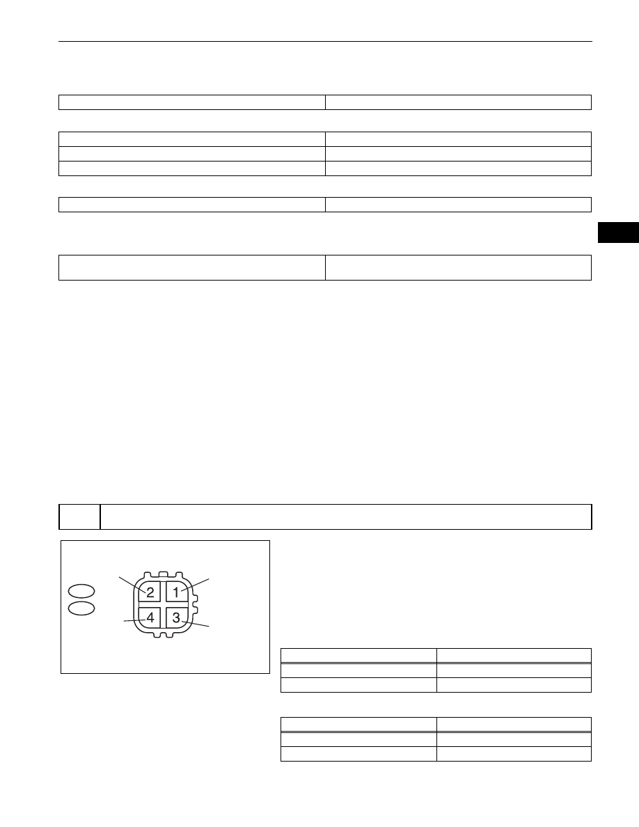
INSPECT HEATED OXYGEN SENSOR (HEATER RESISTANCE)
Component Side:
HO2 Sensor
Front View
B36
B34
*1
*2
+B
E2
HT1B
HT2B
OX1B
OX2B
*1: Bank 1
*2: Bank 2
*1
*2
*1
*2
A133485E01
Tester Connections
Specified Conditions
HT1B (1) - +B (2)
11 to 16
Ω at 20°C (68°F)
HT1B (1) - E2 (4)
10 k
Ω or higher
Tester Connections
Specified Conditions
HT2B (1) - +B (2)
11 to 16
Ω at 20°C (68°F)
HT2B (1) - E2 (4)
10 k
Ω or higher