Toyota FJ Cruiser (GSJ 10, 15 series). Instruction - part 22


  Index      Toyota     Toyota FJ Cruiser (model GSJ 10, 15 series) - service repair instruction 2007 year


Search            copyright infringement  


Content   ..  20  21  22  23   ..


Toyota FJ Cruiser (GSJ 10, 15 series). Instruction - part 22


1GR-FE ENGINE CONTROL SYSTEM  –  SFI SYSTEM

ES–43

ES

FREEZE FRAME DATA

1.

DESCRIPTION
Freeze frame data record the engine conditions (fuel 
system, calculated load, engine coolant temperature, 
fuel trim, engine speed, vehicle speed, etc.) when a 
malfunction is detected. When troubleshooting, it can 
help determine if the vehicle was running or stopped, the 
engine was warmed up or not, the air-fuel ratio was 
LEAN or RICH, and other data, from the time the 
malfunction occurred.
HINT:
If it is impossible to replicate the problem even though a 
DTC is detected, confirm the freeze frame data.
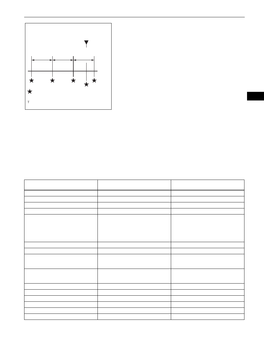
The ECM records engine conditions in the form of freeze 
frame data every 0.5 seconds. Using an intelligent tester, 
five separate sets of freeze frame data, including the 
data values at the time when the DTC was set, can be 
checked.

3 data sets before the DTC was set

1 data set when the DTC was set

1 data set after the DTC was set

These data sets can be used to simulate the conditions 
of the vehicle around the time of the occurrence of the 
malfunction. The data may assist in identifying of the 
cause of the malfunction, and in judging whether it was 
temporary or not.

2.

LIST OF FREEZE FRAME DATA

DTC was set.

0.5 seconds

0.5 seconds

Freeze frame data which can be read

0.5 seconds

A103809E02

LABEL

(Intelligent Tester Display)

Measure Item/Range

Diagnostic Note

INJECTOR

Injector

-

IGN ADVANCE

Ignition advance

-

CALC LOAD

Calculate load

Calculated load by ECM

VEHICLE LOAD

Vehicle load

-

MAF

Mass air flow volume

If value approximately 0.0 g/sec:

Mass air flow meter power source circuit 
open or short

VG circuit open or short
If value 160.0 g/sec or more:

E2G circuit open

ENGINE SPD

Engine speed

-

VEHICLE SPD

Vehicle speed

Speed indicated on speedometer

COOLANT TEMP

Engine coolant temperature

If value -40

°C (-40°F), sensor circuit open

If value 140

°C (284°F) or more, sensor circuit 

shorted

INTAKE AIR

Intake air temperature

If value -40

°C (-40°F), sensor circuit open

If value 140

°C (284°F) or more, sensor circuit 

shorted

AIR-FUEL RATIO

Air-fuel ratio

-

PURGE DENSITY

Learning value of purge density

-

EVAP PURGE FLOW

Purge flow

-

EVAP PURGE VSV

EVAP purge VSV duty ratio

-

KNOCK CRRT VAL

Correction learning value of knocking

-

KNOCK FB VAL

Feedback value of knocking

-

ES–44

1GR-FE ENGINE CONTROL SYSTEM  –  SFI SYSTEM

ES

ACCEL POS #1

Absolute Accelerator Pedal Position (APP) 
No. 1

-

ACCEL POS #2

Absolute APP No. 2

-

THROTTLE POS

Throttle position

Read value with ignition switch ON (Do not 
start engine)

THROTTLE POS

Throttle sensor positioning

Read value with ignition switch ON (Do not 
start engine)

THROTTLE POS #2

Throttle sensor positioning #2

-

THROTTLE MOT

Throttle motor

-

O2S B1 S2

Heated oxygen sensor output voltage

Performing INJ VOL or A/F CONTROL 
function of ACTIVE TEST enables technician 
to check voltage output of sensor

O2S B2 S2

Heated oxygen sensor output voltage

Performing INJ VOL or A/F CONTROL 
function of ACTIVE TEST enables technician 
to check voltage output of sensor

AFS B1 S1

A/F sensor output voltage

Performing INJ VOL or A/F CONTROL 
function of ACTIVE TEST enables technician 
to check voltage output of sensor

AFS B2 S1

A/F sensor output voltage

Performing INJ VOL or A/F CONTROL 
function of ACTIVE TEST enables technician 
to check voltage output of sensor

AFS B2 S1

A/F sensor output current

Performing INJ VOL or A/F CONTROL 
function of ACTIVE TEST enables technician 
to check current output of sensor

TOTAL FT #1

Total fuel trim (Bank 1)

-

TOTAL FT #2

Total fuel trim (Bank 2)

-

SHORT FT #1

Short-term fuel trim (Bank 1)

Short-term fuel compensation used to 
maintain air-fuel ratio at stoichiometric air-fuel 
ratio

LONG FT #1

Long-term fuel trim (Bank 1)

Overall fuel compensation carried out in long-
term to compensate a continual deviation of 
short-term fuel trim from central valve

SHORT FT #2

Short-term fuel trim (Bank 2)

Short-term fuel compensation used to 
maintain air-fuel ratio at stoichiometric air-fuel 
ratio

LONG FT #2

Long-term fuel trim (Bank 2)

Overall fuel compensation carried out in long-
term to compensate a continual deviation of 
short-term fuel trim from central valve

FUEL SYS #1

Fuel system status (Bank1)

OL (Open Loop): Has not yet satisfied 
conditions to go closed loop

CL (Closed Loop): Using heated oxygen 
sensor as feedback for fuel control

OL DRIVE: Open loop due to driving 
conditions (fuel enrichment)

OL FAULT: Open loop due to detected 
system fault

CL FAULT: Closed loop but heated 
oxygen sensor, which used for fuel 
control, malfunctioning

FUEL SYS #2

Fuel system status (Bank2)

OL (Open Loop): Has not yet satisfied 
conditions to go closed loop

CL (Closed Loop): Using heated oxygen 
sensor as feedback for fuel control

OL DRIVE: Open loop due to driving 
conditions (fuel enrichment)

OL FAULT: Open loop due to detected 
system fault

CL FAULT: Closed loop but heated 
oxygen sensor, which used for fuel 
control, malfunctioning

LABEL

(Intelligent Tester Display)

Measure Item/Range

Diagnostic Note

1GR-FE ENGINE CONTROL SYSTEM  –  SFI SYSTEM

ES–45

ES

O2FT B1 S2

Fuel trim at heated oxygen sensor

-

O2FT B2 S2

Fuel trim at heated oxygen sensor

-

AF FT B1 S1

Fuel trim at A/F sensor

-

AFS B1 S1

A/F sensor output current

Performing INJ VOL or A/F CONTROL 
function of ACTIVE TEST enables technician 
to check current output of sensor

AF FT B2 S1

Fuel trim at A/F sensor

-

CAT TEMP B1 S1

Catalyst temperature

-

CAT TEMP B2 S1

Catalyst temperature

-

CAT TEMP B1 S2

Catalyst temperature

-

CAT TEMP B2 S2

Catalyst temperature

-

S O2S B1 S2

Sub heated oxygen sensor impedance

-

S O2S B2 S2

Sub heated oxygen sensor impedance

-

INI COOL TEMP

Initial engine coolant temperature

-

INI INTAKE TEMP

Initial intake air temperature

-

INJ VOL

Injection volume

-

STARTER SIG

Starter signal

-

PS SW

Power steering signal

-

PS SIGNAL

Power steering signal (history)

This signal status usually ON until battery 
terminals disconnected

CTP SW

Closed throttle position switch

-

A/C SIG

A/C signal

-

ELECT LOAD SIG

Electrical load signal

-

STOP LIGHT SW

Stop light switch

-

BATTERY VOLTAGE

Battery voltage

-

ATM PRESSURE

Atmospheric pressure

-

FUEL PMP SP CTL

Fuel pump speed control status

-

ACIS CTRL B2

ACIS VSV status

-

ACT VSV

A/C cut status

-

VVT CTRL B2

VVT control status

-

EVAP (Purge) VSV

EVAP purge VSV

VSV for EVAP controlled by ECM (ground 
side duty control)

FUEL PUMP / SPD

Fuel pump speed status

-

VVT CTRL B1

VVT control status

-

VACUUM PUMP

Key-off EVAP system pump status

-

EVAP VENT VAL

Key-off EVAP system vent valve status

-

TC/TE1

TC and TE1 terminals of DLC3

-

ENG SPEED #1

Engine speed for cylinder 1

-

ENG SPEED #2

Engine speed for cylinder 2

-

ENG SPEED #3

Engine speed for cylinder 3

-

ENG SPEED #4

Engine speed for cylinder 4

-

ENG SPEED #5

Engine speed for cylinder 5

-

ENG SPEED #6

Engine speed for cylinder 6

-

ENG SPEED ALL

Engine speed for all cylinders

-

VVTL AIM ANGL #1

VVT aim angle

-

VVT CHNG ANGL #1

VVT change angle

-

VVT OCV DUTY B1

VVT OCV operation duty

-

VVTL AIM ANGL #2

VVT aim angle

-

VVT CHNG ANGL #2

VVT change angle

-

VVT OCV DUTY B2

VVT OCV operation duty

-

LABEL

(Intelligent Tester Display)

Measure Item/Range

Diagnostic Note

ES–46

1GR-FE ENGINE CONTROL SYSTEM  –  SFI SYSTEM

ES

FC IDL

Idle fuel cut

ON: when throttle valve fully closed and 
engine speed over 3,500 rpm

FC TAU

FC TAU

Fuel cut being performed under very light load 
to prevent engine combustion from becoming 
incomplete

IGNITION

Ignition

-

CYL #1

Cylinder #1 misfire rate

Displayed in only idling

CYL #2

Cylinder #2 misfire rate

Displayed in only idling

CYL #3

Cylinder #3 misfire rate

Displayed in only idling

CYL #4

Cylinder #4 misfire rate

Displayed in only idling

CYL #5

Cylinder #5 misfire rate

Displayed in only idling

CYL #6

Cylinder #6 misfire rate

Displayed in only idling

CYL ALL

All cylinder misfire rate

Displayed in only idling

MISFIRE RPM

Misfire RPM

-

MISFIRE LOAD

Misfire load

-

MISFIRE MARGIN

Margin to detect engine misfire

-

ENG RUN TIME

Accumulated engine running time

-

TIME DTC CLEAR

Cumulative time after DTC cleared

-

DIST DTC CLEAR

Accumulated distance from DTC cleared

-

WU CYC DTC CLEAR

Warm-up cycle after DTC cleared

-

LABEL

(Intelligent Tester Display)

Measure Item/Range

Diagnostic Note


Content   ..  20  21  22  23   ..