Toyota Sequoia (2005). Manual - part 882


  Главная      Automobile - Toyota     Toyota Sequoia - Repair manual 2005 year


поиск по сайту           правообладателям


содержание   ..  880  881  882  883   ..


Toyota Sequoia (2005). Manual - part 882


I04165

2

1

I04166

2

1

–

BODY ELECTRICAL

POWER SEAT CONTROL SYSTEM

BE–113

3517

13.

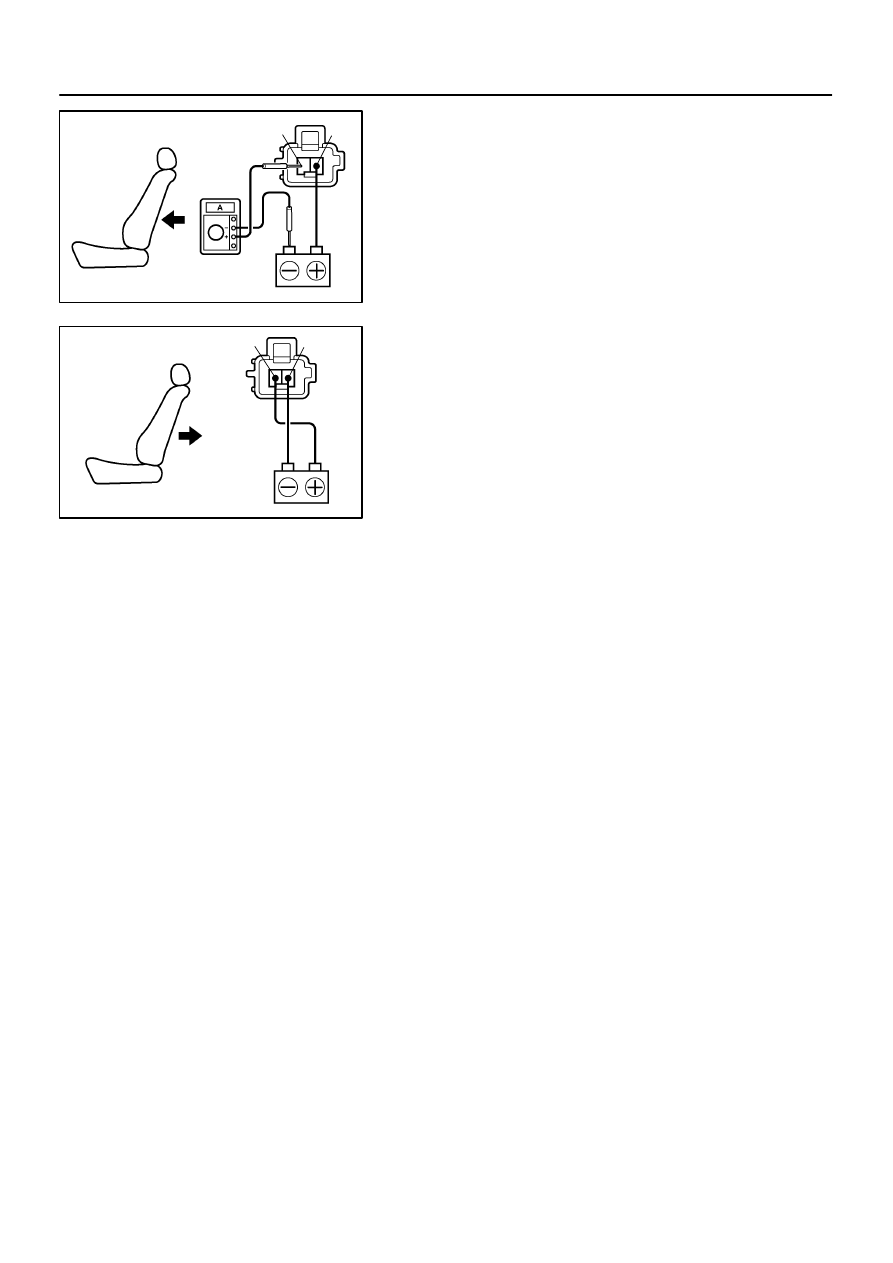
INSPECT LUMBAR SUPPORT MOTOR PTC THERM-
ISTOR OPERATION

(a)

Connect the positive (+) lead from the battery to terminal
2 and the negative (–) lead to terminal 1 on the lumbar
support motor connector and move the lumbar support to
front end position.

(b)

Continue to apply voltage, check that a circuit breaker op-
eration noise can be heard within 4 to 60 seconds.

(c)

Reverse the polarity, check that the lumbar support be-
gins to move to release side within approximately 60 se-
conds.

If operation is not as specified, replace the motor.

BE03G–08

I28419

Outer Mirror Assembly


 Mirror Motor

Instrument Panel J/B

Mirror Switch

Ignition Switch

BE–114

–

BODY ELECTRICAL

POWER MIRROR CONTROL SYSTEM

3518

POWER MIRROR CONTROL SYSTEM

LOCATION

BE2MJ–01

I18656

I18657

Retract 
Mirror

–

BODY ELECTRICAL

POWER MIRROR CONTROL SYSTEM

BE–115

3519

INSPECTION

1.

w/o Retract Mirror and Driving Position Memory:

(a)

Left Side:
INSPECT MIRROR SWITCH CONTINUITY

Switch position

Tester connection

Specified condition

OFF

–

No continuity

UP

4 – 8, 6 – 7

Continuity

DOWN

4 – 7, 6 – 8

Continuity

LEFT

5 – 8, 6 – 7

Continuity

RIGHT

5 – 7, 6 – 8

Continuity

(b)

Right Side:
INSPECT MIRROR SWITCH CONTINUITY

Switch position

Tester connection

Specified condition

OFF

–

No continuity

UP

3 – 8, 6 – 7

Continuity

DOWN

3 – 7, 6 – 8

Continuity

LEFT

2 – 8, 6 – 8

Continuity

RIGHT

2 – 7, 6 – 8

Continuity

If continuity is not as specified, replace the switch.

2.

w/ Retract Mirror only:

(a)

Left Side:
INSPECT MIRROR SWITCH CONTINUITY

Switch position

Tester connection

Specified condition

OFF

–

No continuity

UP

4 – 8, 6 – 7

Continuity

DOWN

4 – 7, 6 – 8

Continuity

LEFT

5 – 8, 6 – 7

Continuity

RIGHT

5 – 7, 6 – 8

Continuity

(b)

Right side:
INSPECT MIRROR SWITCH CONTINUITY

Switch position

Tester connection

Specified condition

OFF

–

No continuity

UP

3 – 8, 6 – 7

Continuity

DOWN

3 – 7, 6 – 8

Continuity

LEFT

5 – 8, 6 – 7

Continuity

RIGHT

5 – 7, 6 – 8

Continuity

If continuity is not as specified, replace the switch.

I28508

I18584

4

5

BE–116

–

BODY ELECTRICAL

POWER MIRROR CONTROL SYSTEM

3520

(c)

INSPECT MIRROR SWITCH CONTINUITY

Switch position

Tester connection

Specified condition

DRIVE

7 – 9, 8 – 10

Continuity

RETRACT

7 – 10, 8 – 9

Continuity

If continuity is not as specified, replace the switch.

3.

w/o Retract Mirror and Driving Position Memory:

(a)

Left Side:
INSPECT MIRROR SWITCH CONTINUITY

Switch position

Tester connection

Specified condition

OFF

1 – 2

10 k

Ω

 or higher

UP

2 – 3

100 

Ω

DOWN

2 – 3

470 

Ω

LEFT

2 – 3

800 

Ω

RIGHT

2 – 3

250 

Ω

(b)

Right Side:
INSPECT MIRROR SWITCH CONTINUITY

Switch position

Tester connection

Specified condition

OFF

1 – 2

10 k

Ω

 or higher

UP

2 – 3

100 

Ω

DOWN

2 – 3

470 

Ω

LEFT

2 – 3

800 

Ω

RIGHT

2 – 3

250 

Ω

If continuity is not as specified, replace the switch.
(c)

INSPECT MIRROR SWITCH CONTINUITY

Switch position

Tester connection

Specified condition

DRIVE

4 – 7, 6 – 8

Continuity

RETRACT

4 – 8, 6 – 7

Continuity

4.

w/ Retract Mirror only:
INSPECT MIRROR MOTOR OPERATION

(a)

Connect the positive (+) lead from the battery to terminal
4 and the negative (–) lead to terminal 5. Check that the
mirror turns leftward.


содержание   ..  880  881  882  883   ..