Toyota Sequoia (2005). Manual - part 645


  Главная      Automobile - Toyota     Toyota Sequoia - Repair manual 2005 year


поиск по сайту           правообладателям


содержание   ..  643  644  645  646   ..


Toyota Sequoia (2005). Manual - part 645


I07839

2

1

–

DIAGNOSTICS

AIR CONDITIONING SYSTEM

DI–2375

2569

INSPECTION PROCEDURE

1

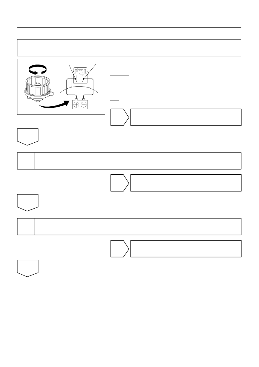
Check blower motor.

PREPARATION:
Remove the blower motor (See page 

AC–50

).

CHECK:
Connect the positive (+) lead connected to terminal 2 of the
blower motor connector, and the negative (–) lead to terminal
1.
OK:

Blower motor operates smoothly.

NG

Replace blower motor.

OK

2

Check harness and connector between battery and blower motor linear control-
ler, blower motor linear controller and body ground (See page 

IN–35

).

NG

Repair or replace harness or connector.

OK

3

Check harness and connector between integration control and panel and blower
motor linear controller (See page 

IN–35

).

NG

Repair or replace harness or connector.

OK

DI–2376

–

DIAGNOSTICS

AIR CONDITIONING SYSTEM

2570

4

Check integration control and panel (See page 

IN–35

).

NG

Replace integration control and panel.

OK

Replace blower motor linear controller.

I28844

Integration Control
and Panel

2

L

16

7

R–W

RrBLW

RrVM

I21

21

BP

BH1

22

G

IJ3

A30
A/C Power Transistor

4

LG

W–G

W–B

5

3

B15
Blower Motor
(Rear)

1

2

G

W–G

L

1

w/ Rear A/C:

From 
RR Heater Relay

I21

IJ3

W–B

A

J57 
J/C

–

DIAGNOSTICS

AIR CONDITIONING SYSTEM

DI–2377

2571

Blower Motor Circuit (Rear A/C)

CIRCUIT DESCRIPTION

This is power source for the blower motor.

WIRING DIAGRAM

DI8AF–06

I28847

RrBLW

I21

Integration Control and Panel:

I24460

DI–2378

–

DIAGNOSTICS

AIR CONDITIONING SYSTEM

2572

INSPECTION PROCEDURE

1

Check voltage between terminal RrBLW of integration control and panel and
body ground.

PREPARATION:
Remove the integration control and panel with connectors still
connected.
CHECK:
(a)

Turn the ignition switch to ON.

(b)

Operate the blower motor.

(c)

Measure the voltage between terminal RrBLW of the in-
tegration control and panel and body ground.

OK:

Voltage: 1 to 3 V

OK

Go to step 3.

NG

2

Check blower motor.

PREPARATION:
Remove the blower motor.
CHECK:
Connect the positive (+) lead from the battery to terminal 2 and
the negative (–) lead to terminal 1 of the blower motor connec-
tor.
OK:

Blower motor operates smoothly.

NG

Replace blower motor.

OK


содержание   ..  643  644  645  646   ..