Toyota Sequoia (2005). Manual - part 598


  Главная      Automobile - Toyota     Toyota Sequoia - Repair manual 2005 year


поиск по сайту           правообладателям


содержание   ..  596  597  598  599   ..


Toyota Sequoia (2005). Manual - part 598
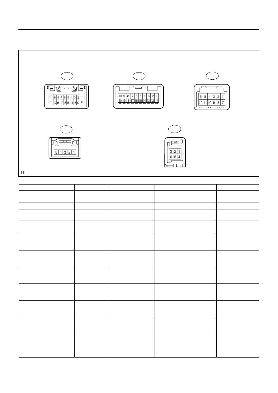


DIDC4–01

I28763

R27

R29

R30

R26

R28

–

DIAGNOSTICS

NAVIGATION SYSTEM

DI–2187

2381

TERMINALS OF ECU

1.

RADIO AND NAVIGATION ASSY

Symbols (Terminal No.)

Wiring Color

Terminal Description

Condition

Specification

ACC (R30–11) – 

GND (R30–20)

GR – BR

Accessory (ON)

Ignition switch OFF

→

ACC or ON

Below 1 V 

→

10 to 14 V

B (R30–1) – GND (R30–20)

L–Y – BR

Battery

Always

10 to 14 V

GND (R30–20) – Body ground

BR – 

Body ground

Ground

Always

Below 1 V

ANT (R30–13) – 

GND (R30–20)

B–R – BR

Power source of antenna

Radio switch ON and AM or FM

10 to 14 V

ILL+ (R30–2) – ILL– (R30–12)

G – W–G

Illumination signal

Ignition switch ON

Light control switch OFF 

→

TAIL or

ON

Below 1 V 

→

10 to 14 V

R+ (R30–8) – GND (R30–20)

W – BR

Sound signal (Right)

Audio system is playing

A waveform synchro-

nized with sound is out-

put

L+ (R30–9) – GND (R30–20)

B – BR

Sound signal (Left)

Audio system is playing

A waveform synchro-

nized with sound is out-

put

R– (R30–18) – GND (R30–20)

G – BR

Sound signal (Right)

Audio system is playing

A waveform synchro-

nized with sound is out-

put

L– (R30–19) – GND (R30–20)

R – BR

Sound signal (Left)

Audio system is playing

A waveform synchro-

nized with sound is out-

put

SWG (R27–6) – Body ground

BR–W – 

Body ground

Steering pad switch

ground

Always

Below 1 V

SW1 (R27–7) – SWG (R27–6)

LG–R – BR–W

Steering pad switch signal

Steering pad switch not operated

→

SEEK+ switch pushed

→

SEEK– switch pushed

→

VOL+ switch pushed

→

VOL– switch pushed

4 V or more

→

Approx. 0.5 V

→

Approx. 0.9 V

→

Approx. 2.0 V

→

Approx. 3.4 V

DI–2188

–

DIAGNOSTICS

NAVIGATION SYSTEM

2382

SW2 (R27–8) – SWG (R27–6)

GR–R – BR–W

Steering pad switch signal

Steering pad switch not operated

→

MODE switch pushed

4 V or more

→

Below 2.5 V

SPD (R29–3) – GND (R30–20)

G–O – BR

Speed signal from com-

bination meter

See ”Vehicle Signal Check Mode”

(See page 

DI–2179

)

–

REV (R29–5) – GND (R30–20)

B–Y – BR

Reverse signal from com-

bination meter

See ”Vehicle Signal Check Mode”

(See page 

DI–2179

)

–

MUTE (R28–7) – 

GND (R30–20)

R–W – BR

MUTE signal 

(From navigation)

Audio system is playing 

→

 chang-

ing mode

Above 3.5 V 

→


Below 1 V

SLD (R30–10) – Body ground

Shielded – 

Body ground

Shield ground

Always

Below 1 V

SWG (R27–6) – Body ground

BR–W – 

Body ground

Steering pad switch

ground

Always

Below 1 V

ATX+ (R30–5) – GND (R30–20)

V – BR

AVC–LAN 

communication signal

Ignition switch ON

2 to 3 V

ATX– (R30–15) – 

GND (R30–20)

P – BR

AVC–LAN 

communication signal

Ignition switch ON

2 to 3 V

IVO+ (R27–11) – 

GND (R30–20)

W – BR

Voice guidance output

signal

Navigation system is voice guid-

ance output

A waveform synchro-

nized with sound is out-

put

IVO– (R27–12) – 

GND (R30–20)

B – BR

Voice guidance output

signal

Navigation system is voice guid-

ance output

A waveform synchro-

nized with sound is out-

put

SLD1 (R27–13) – Body ground

Shielded – 

Body ground

Shield ground

Always

Below 1 V

PKB (R29–1) – GND (R30–20)

LG–R – BR

Parking brake switch sig-

nal

Parking brake pedal is depress 

→

Below 1 V 

→


10 to 14 V

(*1) NTSC (R26–1) – 

GND (R30–20)

R – BR

Display signal (From mul-

ti–display controller)

Navigation display is ON

Pulse generation

(*1) SGD1 (R26–4) – 

Body ground

G – Body ground

Ground

Always

Below 1 V

(*1) SGND (R26–5) – 

Body ground

Shielded – 

Body ground

Shield ground

Always

Below 1 V

(*1, 2) TX+ (R27–9) – 

GND (R30–20)

L – BR

AVC–LAN 

communication signal

Ignition switch ON

2 to 3 V

(*1, 2) TX– (R27–10) – 

GND (R30–20)

LG – BR

AVC–LAN 

communication signal

Ignition switch ON

2 to 3 V

(*1, 2) R–R+ (R27–15) – 

GND (R30–20)

W – BR

Sound signal 

(Right output)

Audio system is playing

A waveform synchro-

nized with sound is out-

put

(*1, 2) R–R– (R27–16) – 

GND (R30–20)

G – BR

Sound signal 

(Right output)

Audio system is playing

A waveform synchro-

nized with sound is out-

put

(*1, 2) R–L+ (R27–17) – 

GND (R30–20)

B – BR

Sound signal (Left output)

Audio system is playing

A waveform synchro-

nized with sound is out-

put

(*1, 2) R–L– (R27–18) – 

GND (R30–20)

R – BR

Sound signal (Left output)

Audio system is playing

A waveform synchro-

nized with sound is out-

put

(*1) RSLD (R27–14) – 

Body ground

Shielded – 

Body ground

Shield ground

Always

Below 1 V

(*1, 2) RMUT (R27–19) – 

GND (R30–20)

R–W – BR

MUTE signal (To multi–

display controller)

Audio system is playing 

→

 chang-

ing mode

Above 3.5 V 

→


Below 1 V

(*1) CDR+ (R28–2) – 

GND (R30–20)

W – BR

Sound signal (Right input)

Rear seat entertainment system is

playing

A waveform synchro-

nized with sound is out-

put

I28722

S10

S9

–

DIAGNOSTICS

NAVIGATION SYSTEM

DI–2189

2383

(*1) CDR– (R28–3) – 

GND (R30–20)

G – BR

Sound signal (Right input)

Rear seat entertainment system is

playing

A waveform synchro-

nized with sound is out-

put

(*1) CDL+ (R28–4) – 

GND (R30–20)

B – BR

Sound signal (Left input)

Rear seat entertainment system is

playing

A waveform synchro-

nized with sound is out-

put

(*1) CDL– (R28–5) – 

GND (R30–20)

R – BR

Sound signal (Left input)

Rear seat entertainment system is

playing

A waveform synchro-

nized with sound is out-

put

(*1) CSLD (R28–1) – 

Body ground

Shielded – 

Body ground

Shield ground

Always

Below 1 V

(*1) MUTE (R28–6) – 

GND (R30–20)

R–G – BR

MUTE signal (From multi–

display controller)

Rear seat entertainment system is

playing 

→

 changing mode

Above 3.5 V 

→


Below 1 V

*1: w/ Rear seat entertainment system
*2: w/ Rear seat audio system
2.

STEREO COMPONENT AMPLIFIER ASSY

Symbols (Terminal No.)

Wiring Color

Terminal Description

Condition

Specification

B+ (S9–1) – E (S9–16)

L–W – BR

Battery

Always

10 to 14 V

RL+ (S9–4) – E (S9–16)

B – BR

Sound signal (Rear Left)

Audio system is playing

A waveform synchro-

nized with sound is out-

put

RR+ (S9–5) – E (S9–16)

R – BR

Sound signal (Rear Right)

Audio system is playing

A waveform synchro-

nized with sound is out-

put

FL+ (S9–2) – E (S9–16)

P – BR

Sound signal (Front Left)

Audio system is playing

A waveform synchro-

nized with sound is out-

put

FR+ (S9–3) – E (S9–16)

LG – BR

Sound signal (Front Right)

Audio system is playing

A waveform synchro-

nized with sound is out-

put

WFL+ (S9–6) – E (S9–16)

L–W – BR

Sound signal (Front Left)

Audio system is playing

A waveform synchro-

nized with sound is out-

put

WFR+ (S9–7) – E (S9–16)

R – BR

Sound signal (Front Right)

Audio system is playing

A waveform synchro-

nized with sound is out-

put

B2+ (S9–10) – E (S9–16)

L–W – BR

Battery

Always

10 to 14 V

RL– (S9–13) – E (S9–16)

Y – BR

Sound signal (Rear Left)

Audio system is playing

A waveform synchro-

nized with sound is out-

put

RR– (S9–14) – E (S9–16)

W – BR

Sound signal (Rear Right)

Audio system is playing

A waveform synchro-

nized with sound is out-

put

GND (S9–15) – Body ground

BR – 

Body ground

Ground

Always

Below 1 V

DI–2190

–

DIAGNOSTICS

NAVIGATION SYSTEM

2384

E (S9–16) – Body ground

BR – 

Body ground

Ground

Always

Below 1 V

FL– (S9–11) – E (S9–16)

V – BR

Sound signal (Front Left)

Audio system is playing

A waveform synchro-

nized with sound is out-

put

FR– (S9–12) – E (S9–16)

L – BR

Sound signal (Front Right)

Audio system is playing

A waveform synchro-

nized with sound is out-

put

WFL– (S9–17) – E (S9–16)

G – BR

Sound signal (Front Left)

Audio system is playing

A waveform synchro-

nized with sound is out-

put

WFR– (S9–18) – E (S9–16)

Y – BR

Sound signal (Front Right)

Audio system is playing

A waveform synchro-

nized with sound is out-

put

MUTE (S10–1) – E (S9–16)

R–W – BR

Mute signal from radio 
receiver

Audio system is sounding 

→

 chang-

ing mode

Above 3.5 V 

→

Below 3.5 V

L– (S10–2) – E (S9–16)

R – BR

Sound signal from radio 
receiver (Left)

Audio system is playing

A waveform synchro-

nized with sound is out-

put

L+ (S10–3) – E (S9–16)

B – BR

Sound signal from radio 
receiver (Left)

Audio system is playing

A waveform synchro-

nized with sound is out-

put

R– (S10–4) – E (S9–16)

G – BR

Sound signal from radio 
receiver (Right)

Audio system is playing

A waveform synchro-

nized with sound is out-

put

R+ (S10–5) – E (S9–16)

W – BR

Sound signal from radio 
receiver (Right)

Audio system is playing

A waveform synchro-

nized with sound is out-

put

SGND (S10–6) – Body ground

Shielded – 

Body ground

Ground

Always

Below 1 V

TX– (S10–19) – E (S9–16)

P – BR

AVC–LAN
communication signal

Turn ignition switch to ACC

2 to 3 V

TX+ (S10–20) – E (S9–16)

V – BR

AVC–LAN
communication signal

Turn ignition switch to ACC

2 to 3 V

ACC (S10–12) – E (S9–16)

GR – BR

Accessory (ON)

Turn ignition switch OFF 

→

ACC

Below 1 V 

→

10 to 14 V

INT– (S10–22) – E (S9–16)

B – BR

Voice guidance signal

Voice guidance

A waveform synchro-

nized with sound is out-

put

INT+ (S10–23) – E (S9–16)

W – BR

Voice guidance signal

Voice guidance

A waveform synchro-

nized with sound is out-

put

3.

MULTI–DISPLAY CONTROLLER ASSY
See page 

DI–2090

4.

REAR SEAT AUDIO CONTROLLER
See page 

DI–2051


содержание   ..  596  597  598  599   ..