Toyota Sequoia (2005). Manual - part 495


  Главная      Automobile - Toyota     Toyota Sequoia - Repair manual 2005 year


поиск по сайту           правообладателям


содержание   ..  493  494  495  496   ..


Toyota Sequoia (2005). Manual - part 495
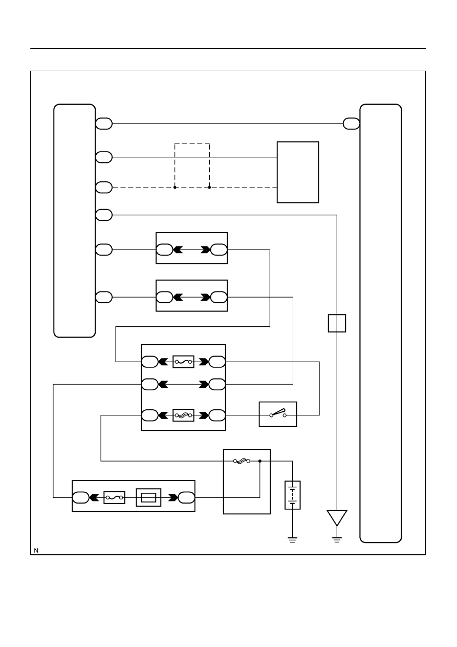


I28589

Glass Breakage 
Sensor ECU

G5 Glass Breakage 
Sensor Microphone

(Shielded)

G4

GBSI

MI+

MI–

GND

GBIG

GB+B

MIC

GND

Body ECU

DOP

B5

G4

G4

G4

G4

G4

Sub J/B No. 4

Sub J/B No. 3

4C

4D

3B

3A

Instrument Panel J/B

F10 
Fusible LB

I18 
Ignition SW

Engine Room J/B

HTR

AM1

1E

1J

1L

1C

1E

1C

ALT

2C

2D

ECU–B Short Pin

Battery

IG

AM1 IG1

J43 
J/C

A

A

8

1

4

5

8

1

2

4

2

6

3

4

1

W–R

W

B

W–L

B

W–R

B–Y

W–R

O

1

1

R–Y

R–Y

3

3

O

1

8

4

6

3

5

P

4

3

9

B

2

1

–

DIAGNOSTICS

BODY CONTROL SYSTEM

DI–1775

1969

WIRING DIAGRAM

DI–1776

–

DIAGNOSTICS

BODY CONTROL SYSTEM

1970

INSPECTION PROCEDURE

1

Check voltage between terminals GBIG, GB+B and GND of glass breakage sen-
sor ECU.

PREPARATION:
Disconnect the glass breakage sensor ECU connector.
CHECK:
Measure the voltage between terminals GB+B and GND of the glass breakage sensor ECU.
OK:

Voltage: 10 to 14 V

PREPARATION:
Turn the ignition switch ON.
CHECK:
Measure the voltage between terminals GBIG and GND of the glass breakage sensor ECU.
OK:

Voltage: 10 to 14 V

NG

 Repair or replace wire harness or connector.

OK

2

Check wire harness and connector between glass breakage sensor ECU and
body ECU (See page 

IN–35

).

NG

Repair or replace harness or connector.

OK

3

Check wire harness and connector between glass breakage sensor ECU and
glass breakage sensor microphone (See page 

IN–35

).

NG

Repair or replace harness or connector.

OK

I28726

G4

I28727

–

DIAGNOSTICS

BODY CONTROL SYSTEM

DI–1777

1971

4

Check glass breakage sensor ECU (microphone output).

PREPARATION:
(a)

Reconnect the glass breakage sensor ECU, glass break-
age sensor microphone and body ECU connectors.

(b)

Connect an oscilloscope to terminal G4–3 of the glass
breakage sensor ECU and body ground.

(c)

Turn the ignition switch ON.

CHECK:
Check the signal waveform according to the condition(s) in the
table below.

Item

Condition

Tool setting

12 V/DIV, 300 ms/DIV

Vehicle condition

Tap the glass breakage sensor micro-

phone with a hard object such as your

fingernail.

OK:

As shown in the illustration.

NG

Replace glass breakage sensor microphone.

HINT:
If the problem recurs even after replacement, replace the glass
breakage sensor ECU.

OK

Proceed to next circuit inspection shown in
problem symptoms table 
(See page 

DI–1686

).

DIDEI–01

DI–1778

–

DIAGNOSTICS

DRIVER DOOR CONTROL SYSTEM

1972

DRIVER DOOR CONTROL SYSTEM

PRECAUTION

NOTICE:
When disconnecting the battery terminal, initialize the following system after the terminal is recon-
nected.

System Name

See Page

Back Door Power Window Control System

BE–77


содержание   ..  493  494  495  496   ..