Toyota Sequoia (2005). Manual - part 444


  Главная      Automobile - Toyota     Toyota Sequoia - Repair manual 2005 year


поиск по сайту           правообладателям


содержание   ..  442  443  444  445   ..


Toyota Sequoia (2005). Manual - part 444
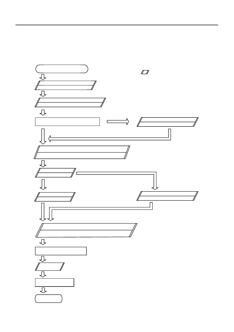


DI1AJ–49

Vehicle Brought to Workshop

Customer Problem Analysis

Check and Clear DTC

Items inside

are titles of pages in this manual,

with the page number in the bottom portion. See
the pages for detailed explanations.

Problem Symptom Confirmation

Symptom Simulation

Symptom
does not occur

Symptom
occurs

DTC Check

Circuit Inspection and Part Inspection

DTC Chart

Problem Symptoms Table

Identification of Problem

Repair

Confirmation Test

End

1

2

3

4

6

7

7

8

9

10

P. 

DI–1572

P. 

DI–1576

P. 

IN–24

P. 

DI–1573

P. 

DI–1576

P. 

DI–1578

P. 

DI–1580

 – 

DI–1599

Multiplex Communication System Inspection *

5

P. 

DI–1904

*: Confirm that there is no trouble


by DTC check.

Normal system code

Trouble code

–

DIAGNOSTICS

ENGINE IMMOBILISER SYSTEM

DI–1571

1765

HOW TO PROCEED WITH TROUBLESHOOTING

HINT:
The ECU of this system is connected to the multiplex communication system. Therefore, before starting trou-
bleshooting, make sure to check that there is no trouble in the multiplex communication system.
Troubleshoot in accordance with the following procedures:

DI1AK–28

ENGINE IMMOBILISER Check Sheet

Inspector’s

Name

:

Customer’s Name

Licence Plate No.

VIN

Production Date

Odometer Reading

/              /

/              /

Frequency Problem Occurs

/                            /

Continuous

Intermittent (       times a day)

DTC Check

1st Time

2nd Time

Normal System Code

Trouble Code (Code         )

Normal SystemCode

Trouble Code (Code         )

Symptoms

km

miles

Engine does not start.

Check Item

Malfunction
Indicator Lamp

Normal

Remains ON

Does not Light Up

Immobiliser is not set.
(Engine starts with key codes other than the registered key code.)

Security indicator is always ON.

Security indicator is always ON. (Although code has been registered in the 
automatic registration mode, indicator is not OFF.)

Security indicator is OFF. 
(When DTC of immobiliser is output)

Security indicator is OFF.
(When DTC of immobiliser is not output)

Security indicator is abnormally blinking.

No code is output.

DI–1572

–

DIAGNOSTICS

ENGINE IMMOBILISER SYSTEM

1766

CUSTOMER PROBLEM ANALYSIS CHECK

DI1AP–40

–

DIAGNOSTICS

ENGINE IMMOBILISER SYSTEM

DI–1573

1767

PROBLEM SYMPTOMS TABLE

Symptom

Suspected Area

See page

Immobiliser is not set.

(Engine starts with key codes other than the registered key code.)

1. Door courtesy light switch circuit (DTC12)

2. Transponder key ECU

DI–1585

IN–35

Engine does not start.

1. Key

2. Key unlock warning switch circuit (DTC11)

3. Transponder key coil

4. Transponder key ECU

5. ECM

*1

DI–1582

BE–143

IN–35

IN–35

Security indicator is always ON.

1. Security indicator

2. Security indicator light circuit

3. Transponder key ECU

*2

DI–1597

IN–35

Security indicator is always ON.

(Although code has been registered in the automatic registration

mode, indicator is not OFF.)

1. Transponder key coil

2. Transponder key ECU

BE–143

IN–35

Security indicator is OFF.

(When DTC of immobiliser is output)

1. Transponder key coil

2. Transponder key ECU

BE–143

IN–35

Security indicator is OFF.

(When DTC of immobiliser is not output)

1. Security indicator light circuit

2. Diagnosis circuit

3. Transponder key ECU

DI–1597

DI–1599

IN–35

Security indicator is abnormally blinking.

Transponder key ECU

IN–35

No code is output.

1. Power source circuit

2. Diagnosis circuit

3. Transponder key ECU

DI–1595

DI–1599

IN–35

*1 : Check that the key which did not start the engine has been registered, and that it is possible to start with
any other already registered key.
*2 : Finish the automatic registration mode because the mode might still be set.

DIABB–02

I24389

T16

Transponder Key ECU:

DI–1574

–

DIAGNOSTICS

ENGINE IMMOBILISER SYSTEM

1768

TERMINALS OF ECU

Symbols (Terminals No.)

Wiring Color

Condition

Specified condition

+B 

↔

 GND

(T16 – 1 

↔

 T16 – 14)

W–R 

↔

 O

Always

10 to 14 V

IG 

↔

 GND

(T16 – 2 

↔

 T16 – 14)

B–O 

↔

 O

Ignition switch ON

10 to 14 V

D 

↔

 GND

W L

O

Ignition switch ON


→


10 to 14 V


→


D 

↔

 GND

(T16 – 3 

↔

 T16 – 14)

W–L 

↔

 O

Ignition switch ON


→


Connect terminals OP3 and CG of DLC3

10 to 14 V


→


Below 2 V

CODE 

↔

 GND

(T16 – 4 

↔

 T16 – 14)

R–Y 

↔

 O

Ignition switch ON

10 to 14 V

RXCK 

↔

 GND

(T16 – 5 

↔

 T16 – 14)

LG 

↔

 O

Ignition switch ON

10 to 14 V

VC12 

↔

 AGND

(T16 – 6 

↔

 T16 – 12)

GR–B 

↔

 GR–L

Always

10 to 14 V

IND 

↔

 GND

LG B

O

Security indicator light is on. (It flashes when the immobiliser

t

i

ti

)

3 to 6 V


→


IND 

↔

 GND

(T16 – 7 

↔

 T16 – 14)

LG–B 

↔

 O

system is operating.)


→


Security indicator light is off.

3 to 6 V


→


Below 1 V

CTY 

↔

 GND

GR L

O

Driver’s door closed


→


10 to 14 V


→


CTY 

↔

 GND

(T16 – 8 

↔

 T16 – 14)

GR–L 

↔

 O

Driver s door closed


→


Driver’s door open

10 to 14 V


→


Below 1 V

KSW 

↔

 GND

Y G

O

Key unlock warning switch ON (Key inserted)


→


Below 1 V


→


KSW 

↔

 GND

(T16 – 9 

↔

 T16 – 14)

Y–G 

↔

 O

Key unlock warning switch ON (Key inserted)


→


Key unlock warning switch OFF (Key not inserted)

Below 1 V


→


10 to 14 V

EFII 

↔

 GND

(T16 –10 

↔

 T16 – 14)

L–Y 

↔

 O

Ignition switch ON

10 to 14 V

EFIO 

↔

 GND

(T16 –11 

↔

 T16 – 14)

P–G 

↔

 O

Ignition switch ON

10 to 14 V

AGND 

↔

 Body ground

(T16 –12 

↔

 Body

ground)

GR–L 

↔

 Body ground

Always

Below 1 V

TXCT 

↔

 GND

(T16 – 13 

↔

 T16 – 14)

Y–G 

↔

 O

Ignition switch ON

10 to 14 V

GND 

↔

 Body ground

(T16 –14 

↔

 Body

ground)

O 

↔

 Body ground

Always

Below 1 V


содержание   ..  442  443  444  445   ..