Toyota Sequoia (2005). Manual - part 326


  Главная      Automobile - Toyota     Toyota Sequoia - Repair manual 2005 year


поиск по сайту           правообладателям


содержание   ..  324  325  326  327   ..


Toyota Sequoia (2005). Manual - part 326


1

2

3

4

5

6

7

8

9 10 11 12 13 14 15 16

F19737

DLC3:

D6

CANH

CANL

–

DIAGNOSTICS

CAN COMMUNICATION SYSTEM

DI–1099

1293

13

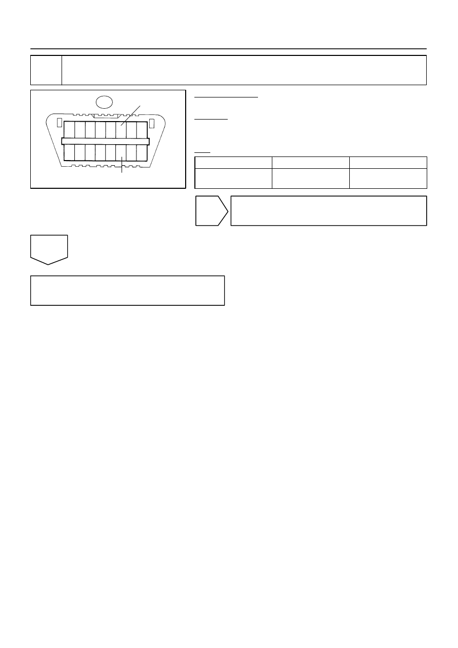
Check CAN bus lines for short circuit (Suspension control ECU sub bus line).

PREPARATION:
Disconnect the suspension control ECU connector (S25).
CHECK:
Measure the resistance according to the value(s) in the table
below.
OK:

Tester connection

Condition

Specified value

D6–6 (CANH) – 

D6–14 (CANL)

Ignition Switch OFF

54 to 69 

Ω

OK

Replace suspension control ECU
(See page 

SA–171

).

NG

Repair or replace suspension control ECU
sub bus line or connector (CAN–H, CAN–L).

F19703

Translate ECU

ENG+

ENG–

GND

14
T5

16
T5

40
T5

W

R

O

1

J55

2

J55

Junction Connector

1

J53

2

J53

W

L

W–B

33
E5

34
E5

7

E8

ECM

CANH

CANL

E01

Suspension 
Control ECU

1

J56

2

J56

W

G

W–B

29

S25

28

22

CANH

CANL

GND

S25

S25

W–B

(*1)

(*1)

A

J12
J/C

IF

EB

D6
DLC3

1

J54

2

J54

B

W

O

O

O

6

14

4

A

A

A

J43
J/C

IG

CANH

CANL

CG

*1: w/ Air Suspension System

DI–1100

–

DIAGNOSTICS

CAN COMMUNICATION SYSTEM

1294

Check CAN Bus Line For Short To GND

CIRCUIT DESCRIPTION

A short to GND is suspected in the CAN bus line when there is continuity between terminals 4 (CG) and 6
(CANH) or terminals 4 (CG) and 14 (CANL) of the DLC3.

Symptom

Trouble Area

There is continuity between terminals 4 (CG) and 6 (CANH)
or terminals 4 (CG) and 14 (CANL) of the DLC3.


Short to GND in CAN bus line


ECM


Translate ECU


Suspension control ECU

WIRING DIAGRAM

DIDIE–01

F19749

Junction Connector ”A” Side
(w/ Earth Terminal)
Wire Harness View:

J54

W

B

Earth Terminal

1

2

3

4

5

6

7

8

9 10 11 12 13 14 15 16

F19737

DLC3:

D6

CANH

CANL

CG

–

DIAGNOSTICS

CAN COMMUNICATION SYSTEM

DI–1101

1295

INSPECTION PROCEDURE

1

Check CAN bus line for short to GND (DLC3 sub bus line).

PREPARATION:
Disconnect the DLC3 sub bus line connector (J54) from the
junction connector.
NOTICE:


Before disconnecting the connector, make a note of
where it is connected.


Reconnect the connector to its original position.

CHECK:
Measure the resistance according to the value(s) in the table
below.
OK:

Tester connection

Condition

Specified value

D6–4 (CG) – 

D6–6 (CANH)

Ignition Switch OFF

1 M

Ω

 or higher

D6–4 (CG) – 

D6–14 (CANL)

Ignition Switch OFF

1 M

Ω

 or higher

NG

Repair or replace DLC3 sub bus line or connec-
tor (CAN–H, CAN–L).

OK

2

Connect the connector.

Reconnect the DLC3 sub bus line connector (J54) to the junction connector.

NEXT

F19749

Junction Connector ”A” Side
(w/ Earth Terminal)
Wire Harness View:

J53

W

L

Earth Terminal

1

2

3

4

5

6

7

8

9 10 11 12 13 14 15 16

F19737

DLC3:

D6

CANH

CANL

CG

DI–1102

–

DIAGNOSTICS

CAN COMMUNICATION SYSTEM

1296

3

Check CAN bus line for short to GND (ECM main bus line).

PREPARATION:
Disconnect the ECM main bus line connector (J53) from the
junction connector.
NOTICE:


Before disconnecting the connector, make a note of
where it is connected.


Reconnect the connector to its original position.

CHECK:
Measure the resistance according to the value(s) in the table
below.
OK:

Tester connection

Condition

Specified value

D6–4 (CG) – 

D6–6 (CANH)

Ignition Switch OFF

3 k

Ω

 or higher

D6–4 (CG) – 

D6–14 (CANL)

Ignition Switch OFF

3 k

Ω

 or higher

OK

Go to step 8.

NG

4

Connect the connector.

Reconnect the ECM main bus line connector (J53) to the junction connector.

NEXT


содержание   ..  324  325  326  327   ..