Toyota Tundra (2015 year). Manual - part 991
Text in Illustration
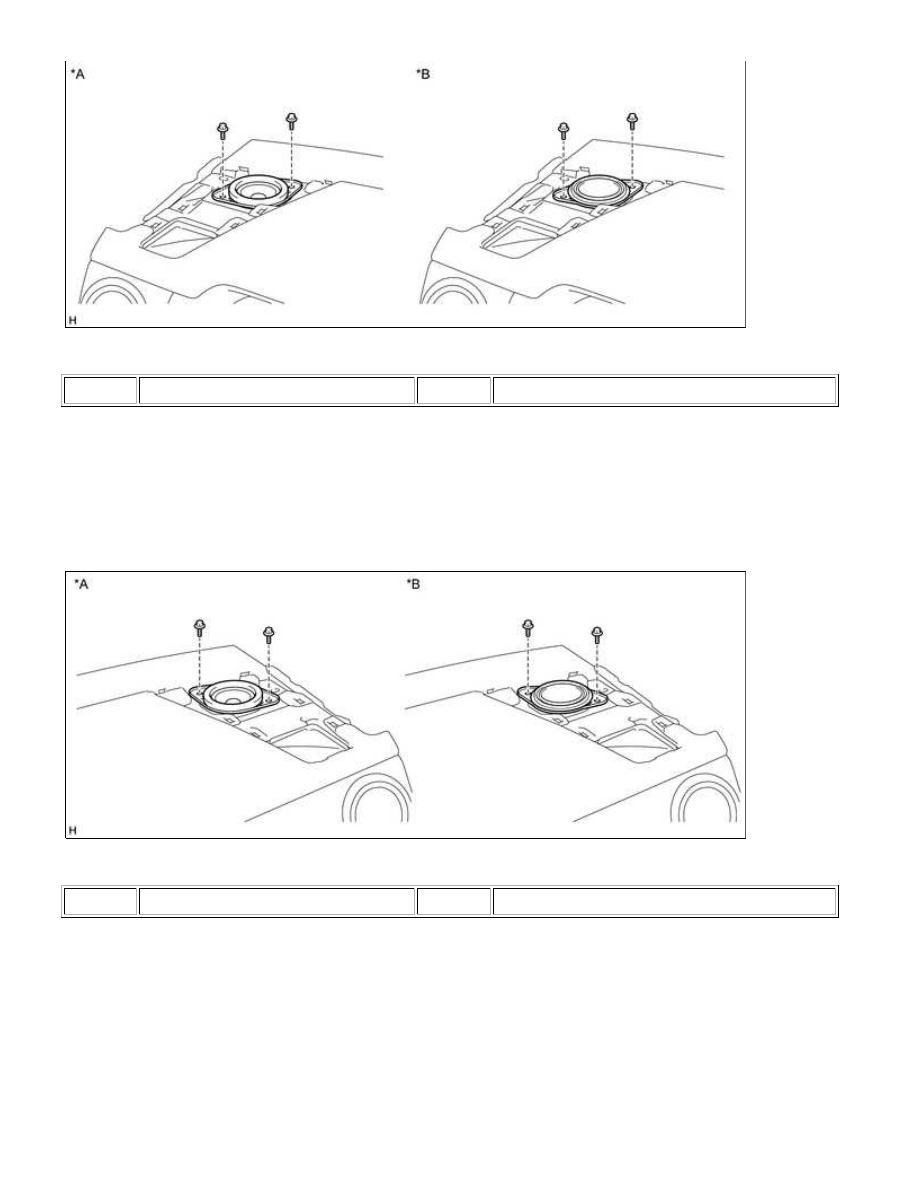
*A
for Standard
*B
for 12 Speakers
(a) Remove the 2 bolts.
(b) Disconnect the connector and remove the front No. 2 speaker assembly LH.
NOTICE:
Text in Illustration
*A
for Standard
*B
for 12 Speakers
(a) Remove the 2 bolts.
(b) Disconnect the connector and remove the front No. 2 speaker assembly RH.
NOTICE: