Toyota Tundra (2015 year). Manual - part 606


  Index      Toyota     Toyota Tundra (2015 year) - Service and Repair Manual


Search            copyright infringement  


Content   ..  604  605  606  607   ..


Toyota Tundra (2015 year). Manual - part 606


OK

Standard resistance:

TESTER CONNECTION

CONDITION

SPECIFIED CONDITION

13 (SLT+) - 5 (SLT-)

20°C (68°F)

5.0 to 5.6 Ω

13 (SLT+) - Body ground

Always

10 kΩ or higher

5 (SLT-) - Body ground

Always

10 kΩ or higher

NG

GO TO STEP 3

2.

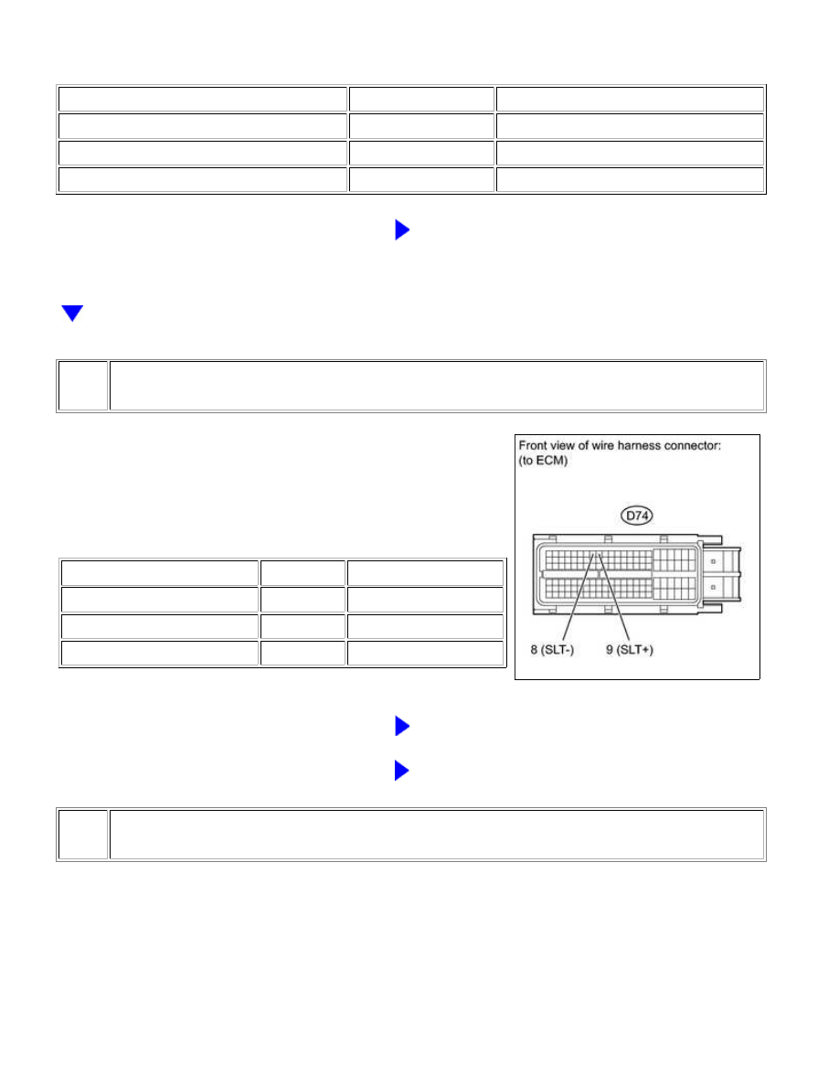
CHECK HARNESS AND CONNECTOR (NO. 1 TRANSMISSION WIRE - ECM)

(a) Disconnect the D74 ECM connector.

(b) Measure the resistance according to the value(s) in the table

below.

Standard resistance:

TESTER CONNECTION

CONDITION

SPECIFIED CONDITION

D74-9 (SLT+) - D74-8 (SLT-)

20°C (68°F) 5.0 to 5.6 Ω

D74-9 (SLT+) - Body ground

Always

10 kΩ or higher

D74-8 (SLT-) - Body ground

Always

10 kΩ or higher

NG

REPAIR OR REPLACE HARNESS OR CONNECTOR

OK

REPLACE ECM

3.

INSPECT SHIFT SOLENOID VALVE SLT

AB60E AUTOMATIC TRANSMISSION: AUTOMATIC TRANSMIS...

(a) Remove shift solenoid valve SLT.

(b) Measure the resistance according to the value(s) in the table

below.

Standard resistance:

TESTER CONNECTION

CONDITION

SPECIFIED CONDITION

1 - 2

20°C (68°F)

5.0 to 5.6 Ω

(c) Connect the battery's positive (+) lead with a 21 W bulb to

Valve moves and makes an operating noise.

NG

REPLACE SHIFT SOLENOID VALVE SLT

OK

REPAIR OR REPLACE NO. 1 TRANSMISSION WIRE

AB60E AUTOMATIC TRANSMISSION: AUTOMATIC TRANSMIS...

Last Modified: 9-16-2014

6.6 C

Doc ID: RM0000012XR098X

Model Year: 2015

Model: Tundra

Prod Date Range: [08/2014 -           ]

Title: AB60E AUTOMATIC TRANSMISSION: AUTOMATIC TRANSMISSION SYSTEM: P2742,P2743; Transmission

Fluid Temperature Sensor "B" Circuit Low Input; 2015 MY Tundra [08/2014 -        ]

DTC

P2742

Transmission Fluid Temperature Sensor "B" Circuit Low Input

DTC

P2743

Transmission Fluid Temperature Sensor "B" Circuit High Input

DESCRIPTION

If the ECM detects an abnormally high ATF temperature near this sensor, the ATF temperature warning light

illuminates or a message is displayed in the combination meter.

HINT:

below.

NO. 2 ATF

TEMPERATURE

SENSOR STATE

DETECTION

CONDITION

SYMPTOM

RECOVERY CONDITION

Sensor is normal

ATF temperature

more than 150°C

(302°F)

ATF temperature warning light is

illuminated or message is displayed

in combination meter

ATF temperature less than

135°C (275°F)*1

ATF temperature

more than 130°C

(266°F)

Shift point too high

ATF temperature less than

110°C (230°F)

When the conditions

(a) and (b) are

satisfied.

(a) ATF temperature

more than 130°C

(266°F)

(b) Engine coolant

temperature more

than 95°C (203°F)

Lock-up at 3rd gear*2

ATF temperature less than

110°C (230°F)*1 and engine

coolant temperature more

than 95°C (203°F)

Sensor is short-

circuited

Any conditions

ATF temperature warning

light blinks or message is

displayed in combination

meter

Symptoms still occur

AB60E AUTOMATIC TRANSMISSION: AUTOMATIC TRANSMIS...

NO. 2 ATF

TEMPERATURE

SENSOR STATE

DETECTION

CONDITION

SYMPTOM

RECOVERY CONDITION

Shift point too high

Engine coolant

temperature more

than 95°C (203°F)

Lock-up at 3rd gear*2

Symptoms still occur

HINT:

*1: When ATF temperature is in the normal range, it decreases to less than 135°C (275°F) within 5

minutes with the shift lever in P or N in an idling state.

*2: When ATF temperature is normal, transmission lock-up occurs in 5th or 6th gear with the shift lever in

the D position or S6 range, in 5th gear with the shift lever in the S5 range, and 4th gear with the shift
lever in the S4 range.

DTC

CODE

DTC DETECTION CONDITION

TROUBLE AREA

P2742

No. 2 ATF temperature sensor resistance is less than 25 Ω

(0.046 V) for 0.5 seconds or more. (1-trip detection logic)

Short in No. 2 ATF

temperature sensor circuit

No. 1 transmission wire

(No. 2 ATF temperature

sensor)

ECM

P2743

No. 2 ATF temperature sensor resistance is higher than 156 kΩ

(4.915 V) for 0.5 sec. or more and either condition is met

(1-trip detection logic):

(A) 15 min. or more have elapsed after the engine start when

the engine coolant temperature or intake air temperature is

-29.375°C (-20.875°F) or less.

(B) 10 sec. or more have elapsed after the engine start when

the engine coolant temperature and intake air temperature are

higher than -29.375°C (-20.875°F).

Open in No. 2 ATF

temperature sensor circuit

No. 1 transmission wire

(No. 2 ATF temperature

sensor)

ECM

MONITOR DESCRIPTION

The ATF temperature sensor converts the ATF temperature into an electrical resistance value. Based on the

resistance, the ECM determines the ATF temperature, and the ECM detects an open or short in the ATF

temperature warning light blinks or a message is displayed in the combination meter.

HINT:

Refer to DTC P0712 


.

AB60E AUTOMATIC TRANSMISSION: AUTOMATIC TRANSMIS...


Content   ..  604  605  606  607   ..