Toyota Tundra (2015 year). Manual - part 579


  Index      Toyota     Toyota Tundra (2015 year) - Service and Repair Manual


Search            copyright infringement  


Content   ..  577  578  579  580   ..


Toyota Tundra (2015 year). Manual - part 579


The output speed sensor SP2 monitors the output shaft speed. The ECM controls the gear shift point and the lock

up timing based on the signals from the output speed sensor SP2 and throttle position sensor.

If the ECM detects no signal from the output speed sensor SP2 even while the vehicle is moving, it will conclude
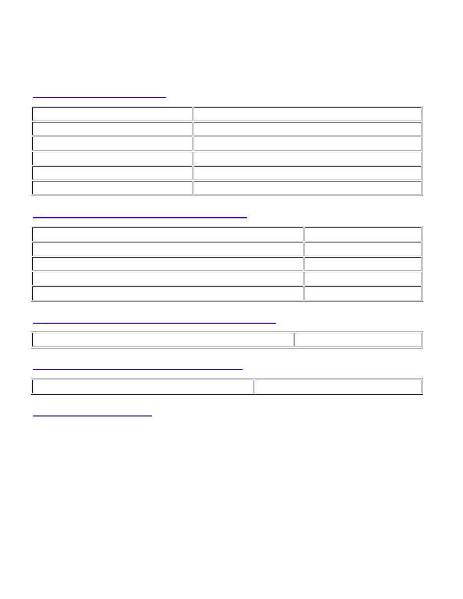
Related DTCs

P0722: Speed sensor SP2/Verify pulse input

Required Sensors/Components

Speed sensor (SP2)

Duration

5 seconds

MIL operation

2 driving cycles

TYPICAL ENABLING CONDITIONS

The monitor will run whenever the following DTCs are not present

None

Vehicle speed at vehicle speed sensor

9 km/h (5.59 mph) or more

Battery voltage

8 V or more

Ignition switch

ON

Starter

OFF

TYPICAL MALFUNCTION THRESHOLDS

Speed sensor signal

No signal

COMPONENT OPERATING RANGE

Vehicle speed at output speed sensor

9 km/h (5.59 mph) or more

WIRING DIAGRAM

AB60E AUTOMATIC TRANSMISSION: AUTOMATIC TRANSMIS...

INSPECTION PROCEDURE

NOTICE:

Perform the universal trip to clear permanent DTCs 


.

1. DATA LIST

HINT:

NOTICE:

In the table below, the values listed under "Normal Condition" are reference values. Do not depend solely

on these reference values when deciding whether a part is faulty or not.

(a) Warm up the engine.

(b) Turn the ignition switch off.

(c) Connect the Techstream to the DLC3.

(d) Turn the ignition switch to ON.

(e) Turn the Techstream on.

(f) Enter the following menus: Powertrain / Engine and ECT / Data List.

(g) According to the display on the Techstream, read the Data List.

Engine and ECT:

TESTER

DISPLAY

MEASUREMENT

ITEM/RANGE

NORMAL CONDITION

DIAGNOSTIC

NOTE

SPD (SP2)

Output shaft speed/

Min.: 0 km/h (0 mph)

Max.: 255 km/h (158

Vehicle stopped: 0 km/h (0 mph) (output shaft speed

is equal to vehicle speed)

-

AB60E AUTOMATIC TRANSMISSION: AUTOMATIC TRANSMIS...

OK

TESTER

DISPLAY

MEASUREMENT

ITEM/RANGE

NORMAL CONDITION

DIAGNOSTIC

NOTE

mph)

HINT:

SPD (SP2) is always 0 while driving:

Open or short in the sensor or circuit.

The SPD (SP2) value displayed on the Techstream is much lower than the actual vehicle speed:

Sensor trouble, improper installation, or intermittent connection trouble in the circuit.

PROCEDURE

1.

INSPECT SPEED SENSOR SP2 INSTALLATION

(a) Check the speed sensor SP2 installation.

OK:

The installation bolt is tightened properly and there is no

clearance between the sensor and transmission case.

NG

SECURELY INSTALL OR REPLACE SPEED SENSOR

SP2

2.

INSPECT SPEED SENSOR SP2

AB60E AUTOMATIC TRANSMISSION: AUTOMATIC TRANSMIS...

OK

(a) Disconnect the D66 speed sensor connector.

(b) Measure the resistance according to the value(s) in the table below.

Standard resistance:

TESTER CONNECTION

CONDITION

SPECIFIED CONDITION

1 - 2

20°C (68°F)

560 to 680 Ω

NG

REPLACE SPEED SENSOR SP2

3.

CHECK HARNESS AND CONNECTOR (SPEED SENSOR SP2 - ECM)

(a) Disconnect the D74 ECM connector.

(b) Measure the resistance according to the value(s) in the table below.

Standard resistance:

AB60E AUTOMATIC TRANSMISSION: AUTOMATIC TRANSMIS...


Content   ..  577  578  579  580   ..