Toyota Tundra (2015 year). Manual - part 407


  Index      Toyota     Toyota Tundra (2015 year) - Service and Repair Manual


Search            copyright infringement  


Content   ..  405  406  407  408   ..


Toyota Tundra (2015 year). Manual - part 407


Last Modified: 9-16-2014

6.6 G

Doc ID: RM0000030G604OX

Model Year: 2015

Model: Tundra

Prod Date Range: [08/2014 -           ]

Title: A760E AUTOMATIC TRANSMISSION: SHIFT LEVER ASSEMBLY (for Floor Shift Type): INSPECTION; 2015

MY Tundra [08/2014 -        ]

INSPECTION

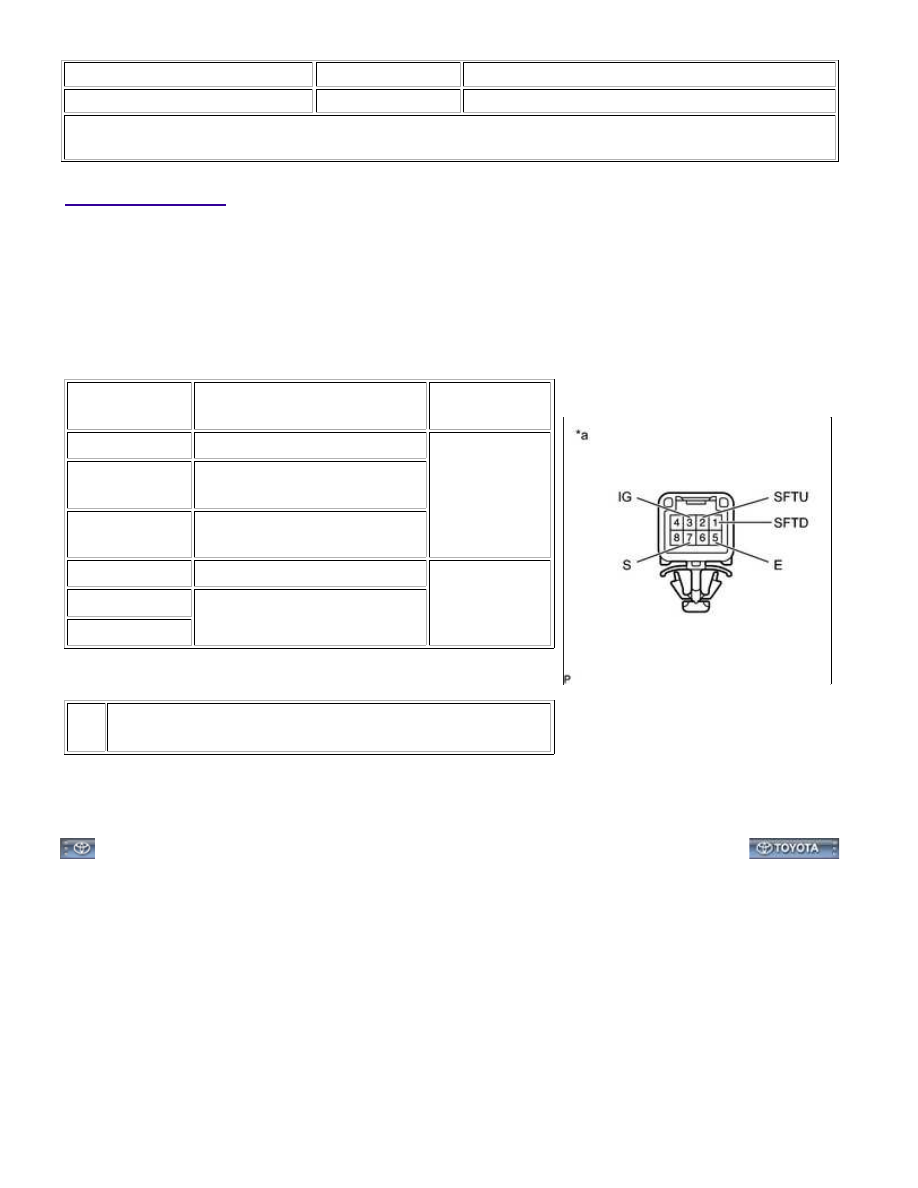
1. INSPECT TRANSMISSION CONTROL SWITCH

(a) Disconnect the transmission control switch connector.

(b) Measure the resistance according to the value(s) in the table

below.

Standard Resistance:

TESTER

CONNECTION

CONDITION

SPECIFIED

CONDITION

3 (IG) - 7 (S)

Shift lever position S, "+" or "-"

Below 1 Ω

2 (SFTU) - 5 (E)

Shift lever position continuously

shifted to "+" (Up-shift)

1 (SFTD) - 5 (E)

Shift lever position continuously

shifted to "-" (Down-shift)

3 (IG) - 7 (S)

Shift lever position not in S

10 kΩ or higher

2 (SFTU) - 5 (E)

Shift lever position S

1 (SFTD) - 5 (E)

Text in Illustration

*a

Component without harness connected

(Transmission Control Switch)

If the result is not as specified, replace the transmission floor

shift assembly.

A760E AUTOMATIC TRANSMISSION: SHIFT LEVER ASSEMBLY ...

Last Modified: 9-16-2014

6.6 N

Doc ID: RM000002YBC02AX

Model Year: 2015

Model: Tundra

Prod Date Range: [08/2014 -           ]

Title: A760E AUTOMATIC TRANSMISSION: SHIFT LEVER ASSEMBLY (for Floor Shift Type): ADJUSTMENT; 2015

MY Tundra [08/2014 -        ]

ADJUSTMENT

1. INSPECT SHIFT LEVER POSITION

(a) When moving the shift lever from N to other positions, check that the lever can be moved smoothly and

accurately to each position and that the position indicator comes on in accordance with the shift lever

position.

If the indicator and shift lever position do not match, carry out the following adjustment procedures.

2. ADJUST SHIFT LEVER POSITION

(a) Move the shift lever to N.

(b) Fold back the transmission control cable adjust case cover. Then

while sliding the slider toward the cable end side, press out the

lock piece from the back side to release the lock.

Text in Illustration

*1

Lock Piece

*2

Slider

set the lock.

Text in Illustration

*1

Lock Piece

*2

Slider

NOTICE:

(e) Inspect the shift lever operation after the adjustment.

A760E AUTOMATIC TRANSMISSION: SHIFT LEVER ASSEMBLY ...

Last Modified: 9-16-2014

6.6 A

Doc ID: RM000002YBH03TX

Model Year: 2015

Model: Tundra

Prod Date Range: [08/2014 -           ]

Title: A760E AUTOMATIC TRANSMISSION: SHIFT LEVER ASSEMBLY (for Floor Shift Type): REASSEMBLY; 2015

MY Tundra [08/2014 -        ]

REASSEMBLY

1. INSTALL SHIFT LOCK CONTROL ECU

(a) Attach the 3 claws to install the shift lock control ECU to the shift lever assembly.

(b) Connect the shift lock solenoid connector.

2. INSTALL POSITION INDICATOR LED

(a) Attach the claw to install the position indicator LED to the lower position indicator housing.

3. INSTALL INDICATOR LIGHT WIRE SUB-ASSEMBLY

(a) Connect the connector and install the indicator light wire sub-assembly to the lower position indicator

housing.

4. INSTALL LOWER POSITION INDICATOR HOUSING

(a) Attach the 4 claws to install the lower position indicator housing

to the shift lever assembly.

5. CONNECT INDICATOR LIGHT WIRE SUB-ASSEMBLY

(a) Attach the 4 guides.

A760E AUTOMATIC TRANSMISSION: SHIFT LEVER ASSEMBLY ...

(b) Securely connect the 2 wire terminals to terminals 4 (ILL+) and

Text in Illustration

*1

Connector Housing Retainer

*a

Component without harness connected

(Transmission Control Switch)

6. INSTALL NO. 2 POSITION INDICATOR SLIDE COVER

(a) Install the No. 2 position indicator slide cover to the position indicator slide cover.

7. INSTALL POSITION INDICATOR SLIDE COVER

(a) Install the position indicator slide cover with the No. 2 position indicator slide cover to the shift lever

assembly.

HINT:

Install the position indicator slide cover so that its mark faces the vehicle front.

8. INSTALL UPPER POSITION INDICATOR HOUSING

(a) Attach the 4 claws to install the upper position indicator housing to the shift lever assembly.

9. INSTALL SHIFT LEVER CAP

(a) Attach the 2 claws to install the shift lever cap to the shift lever

assembly.

A760E AUTOMATIC TRANSMISSION: SHIFT LEVER ASSEMBLY ...


Content   ..  405  406  407  408   ..