Toyota Tundra (2015 year). Manual - part 2972


  Index      Toyota     Toyota Tundra (2015 year) - Service and Repair Manual


Search            copyright infringement  


Content   ..  2970  2971  2972  2973   ..


Toyota Tundra (2015 year). Manual - part 2972


Last Modified: 9-16-2014

6.6 U

Doc ID: RM0000014DJ0BIX

Model Year: 2015

Model: Tundra

Prod Date Range: [08/2014 -           ]

Title: SEAT BELT: SEAT BELT WARNING SYSTEM: TERMINALS OF ECU; 2015 MY Tundra [08/2014 -        ]

TERMINALS OF ECU

1. CHECK COMBINATION METER ASSEMBLY

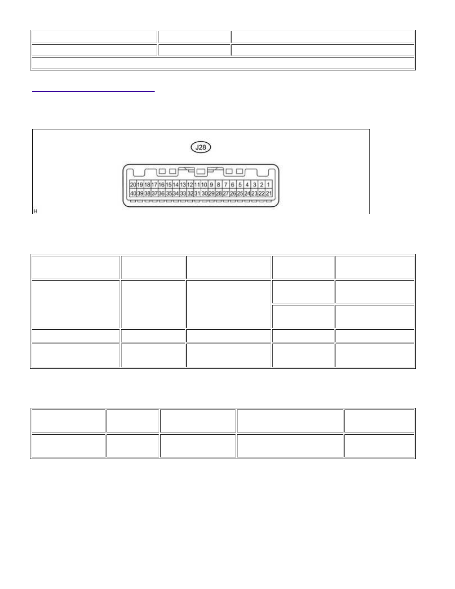
(a) Disconnect the J28 combination meter assembly connector.

(b) Disconnect the J28 combination meter assembly connector.

(c) Measure the resistance and voltage according to the value(s) in the table below.

TERMINAL NO. (SYMBOL)

WIRING COLOR

TERMINAL

DESCRIPTION

CONDITION

SPECIFIED

CONDITION

J28-2 (IG+) - Body

ground

P - Body ground

Ignition power supply

(IG signal)

Ignition switch

off

Below 1 V

Ignition switch

ON

11 to 14 V

J28-1 (B) - Body ground

LG - Body ground Battery power supply

Always

11 to 14 V

J28-24 (ES) - Body

ground

W-B - Body

ground

Ground

Always

Below 1 Ω

(d) Reconnect the J28 combination meter assembly connector.

(e) Measure the voltage according to the value(s) in the table below.

TERMINAL NO.

(SYMBOL)

WIRING

COLOR

TERMINAL

DESCRIPTION

CONDITION

SPECIFIED

CONDITION

J28-30 (SI) - Body

ground

LG - Body

ground

Speed signal (input)

Ignition switch ON, wheel

turned slowly

Pulse generation

2. CHECK CENTER AIRBAG SENSOR ASSEMBLY

SEAT BELT: SEAT BELT WARNING SYSTEM: TERMINALS OF ECU;...

TERMINAL NO.

TERMINAL SYMBOL

DESTINATION

P1-11

DBE+

Front seat inner belt assembly LH

P1-12

DBE-

Front seat inner belt assembly LH

Q1-12

FSP+

Occupant detection ECU

Q1-13

FSP-

Occupant detection ECU

3. CHECK OCCUPANT DETECTION ECU

(a) Measure the voltage according to the value(s) in the table below.

HINT:

TERMINAL NO.

(SYMBOL)

WIRING

COLOR

TERMINAL DESCRIPTION

CONDITION

SPECIFICATION

Y2-1 (+B) - Y2-3

(GND)

W - W-B

Battery

Ignition switch ON

11 to 14 V

Y2-2 (DIA) -

Y2-3 (GND)

GR - W-B

Diagnosis (DLC3)

Ignition switch ON

Pulse

generation

Y2-3 (GND) -

Body ground

W-B - Body

ground

Ground

Always

Below 1 Ω

Y2-4 (FSR-) -

Y2-3 (GND)

Y - W-B

Center airbag sensor

communication ground line

Always

Below 1 Ω

SEAT BELT: SEAT BELT WARNING SYSTEM: TERMINALS OF ECU;...

TERMINAL NO.

(SYMBOL)

WIRING

COLOR

TERMINAL DESCRIPTION

CONDITION

SPECIFICATION

Y2-5 (BGND) -

Y2-3 (GND)

P - W-B

Passenger side buckle switch

ground line

Always

Below 1 Ω

Y2-7 (IG2) -

Y2-3 (GND)

B - W-B

Power source (IGN fuse)

Ignition switch ON

11 to 14 V

Y2-8 (FSR+) -

Y2-4 (FSR-)

L - Y

Center airbag sensor

communication line

Ignition switch ON

Pulse

generation

Y2-9 (BSW) -

Y2-5 (BGND)

G - P

Passenger side buckle switch

line

Ignition switch ON, buckle switch

ON

0.12 to 0.18 A

Ignition switch ON, buckle switch

OFF

0.4 to 0.7 mA

Y1-1 (SGD1) -

Y2-3 (GND)

G - W-B

Front occupant detection

sensor LH ground line

Always

Below 1 Ω

Y1-2 (SGD2) -

Y2-3 (GND)

O - W-B

Front occupant detection

sensor RH ground line

Always

Below 1 Ω

Y1-3 (SGD3) -

Y2-3 (GND)

W - W-B

Rear occupant detection

sensor LH ground line

Always

Below 1 Ω

Y1-4 (SGD4) -

Y2-3 (GND)

BR - W-B

Rear occupant detection

sensor RH ground line

Always

Below 1 Ω

Y1-11 (SVC1) -

Y1-1 (SGD1)

R - G

Front occupant detection

sensor LH power supply line

Ignition switch ON, load is

applied to front occupant

detection sensor LH

4.5 to 5.1 V

Y1-12 (SVC2) -

Y1-2 (SGD2)

W - O

Front occupant detection

sensor RH power supply line

Ignition switch ON, load is

applied to front occupant

detection sensor RH

4.5 to 5.1 V

Y1-5 (SVC3) -

Y1-3 (SGD3)

GR - W

Rear occupant detection

sensor LH power supply line

Ignition switch ON, load is

applied to rear occupant

detection sensor LH

4.5 to 5.1 V

Y1-6 (SVC4) -

Y1-4 (SGD4)

V - BR

Rear occupant detection

sensor RH power supply line

Ignition switch ON, load is

applied to rear occupant

detection sensor RH

4.5 to 5.1 V

Y1-7 (SIG1) -

Y1-1 (SGD1)

P - G

Front occupant detection

sensor LH signal line

Ignition switch ON, load is

applied to front occupant

detection sensor LH

Pulse

generation

Y1-8 (SIG2) -

Y1-2 (SGD2)

L - O

Front occupant detection

sensor RH signal line

Ignition switch ON, load is

applied to front occupant

detection sensor RH

Pulse

generation

Y1-9 (SIG3) -

Y1-3 (SGD3)

Y - W

Rear occupant detection

sensor LH signal line

Ignition switch ON, load is

applied to rear occupant

detection sensor LH

Pulse

generation

Y1-10 (SIG4) -

Y1-4 (SGD4)

B - BR

Rear occupant detection

sensor RH signal line

Ignition switch ON, load is

applied to rear occupant

detection sensor RH

Pulse

generation

SEAT BELT: SEAT BELT WARNING SYSTEM: TERMINALS OF ECU;...

SEAT BELT: SEAT BELT WARNING SYSTEM: TERMINALS OF ECU;...


Content   ..  2970  2971  2972  2973   ..