Content .. 2680 2681 2682 2683 ..
Toyota Tundra (2015 year). Manual - part 2682
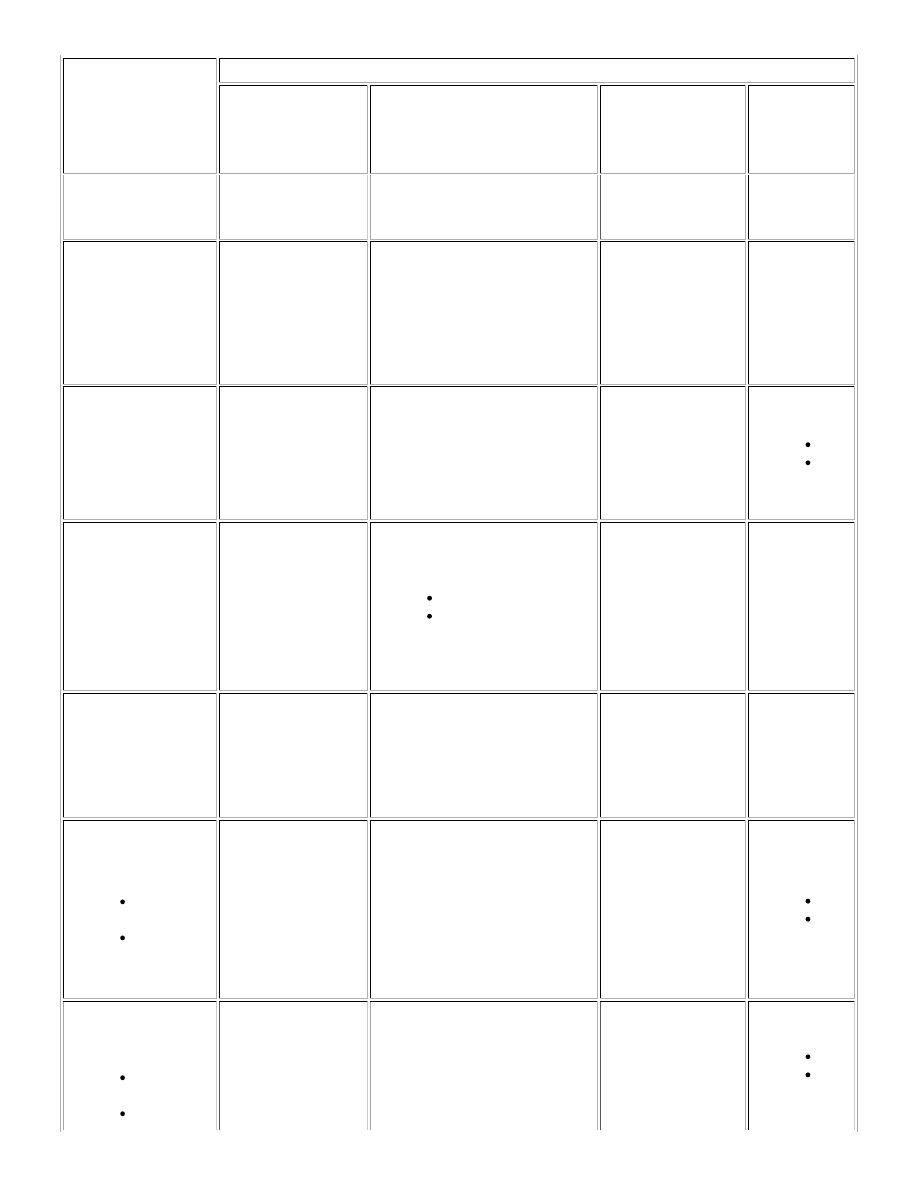
FUNCTION
BEHAVIOR DURING CAN FAILURE
CONTROL
MASTER
1.
SYSTEM
RELATED
2.
VEHICLE BEHAVIOR
INDICATOR AND
BUZZER
DIAGNOSTIC
TROUBLE CODE
spot monitor
sensor
RH/LH
Relay Function
(Transmits relay frames
and does not transmit
non-relay frames.)
Network
gateway
ECU
1.
ECUs
connected to
V bus and V2
bus
2.
CAN controller is reset.
Nothing
Nothing
Diagnostic Function
(Determines the
connection and
communication status of
ECUs which are
connected to the V2
bus.)
Network
gateway
ECU
1.
ECUs
connected to
V2 bus
2.
CAN controller is reset.
Nothing
U0233
U1002
NM Function
(Performs
communication via NM
frames with ECUs that
are equipped with NM,
and controls the CAN
communication
sleep/wake up
functions.)
Network
gateway
ECU
1.
ECUs with
NM functions
connected to
V bus and V2
bus
2.
CAN controller is reset.
Enter LimpHome mode.
Nothing
Nothing
CCP Function
(Communicates with
tools connected via the
V bus and monitors the
RAM in the gateway
ECU.)
Network
gateway
ECU
1.
Tools
connected
via V bus
2.
CAN controller is reset.
Nothing
Nothing
Calculates the operation
condition using the
following information
Vehicle speed
information
Brake
pressure
information
Brake
control with
bracket
relay
1.
ECM, Brake
actuator
assembly
(skid control
ECU)
2.
Maintains the last valid information
from before communication
stopped.
Warning displayed on
multi-information
display.
U0101
U0129
Calculates the wheel slip
condition using the
following information
Vehicle speed
information
Brake
Brake
control with
bracket
relay
1.
ECM, Brake
actuator
2.
Maintains the last valid information
from before communication
stopped.
Warning displayed on
multi-information
display.
U0101
U0129
CAN COMMUNICATION: CAN COMMUNICATION SYSTEM: FAIL-...