Toyota Tundra (2015 year). Manual - part 2571


  Index      Toyota     Toyota Tundra (2015 year) - Service and Repair Manual


Search            copyright infringement  


Content   ..  2569  2570  2571  2572   ..


Toyota Tundra (2015 year). Manual - part 2571
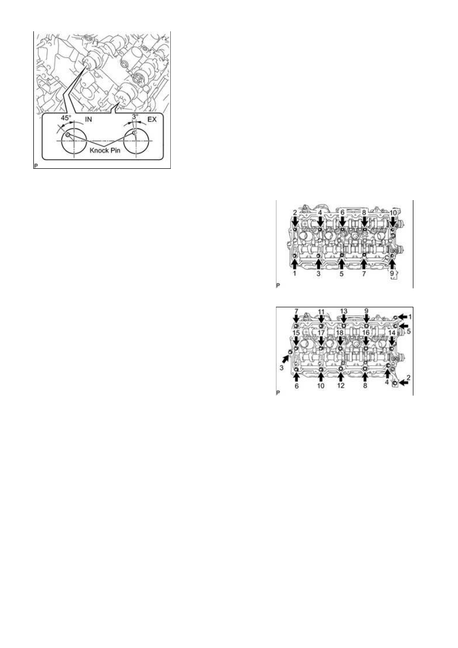


sequence shown in the illustration.

(c) Uniformly loosen and remove the 18 bearing cap bolts in the

sequence shown in the illustration.

NOTICE:

Uniformly loosen the bolts while keeping the camshaft level.

(d) Remove the 6 bearing caps.

HINT:

Arrange the removed parts in the correct order.

(e) Remove the No. 3 and No. 4 camshafts.

HINT:

Arrange the removed parts in the correct order.

35. REMOVE CAMSHAFT HOUSING SUB-ASSEMBLY LH

3UR-FE ENGINE MECHANICAL: ENGINE UNIT: DISASSEMBLY; ...

(a) Remove the camshaft housing by prying between the

cylinder head and camshaft housing with a screwdriver.

NOTICE:

HINT:

Tape the screwdriver tip before use.

36. REMOVE CAMSHAFT BEARING CAP RH

sequence shown in the illustration.

(c) Uniformly loosen and remove the 18 bearing cap bolts in the

sequence shown in the illustration.

NOTICE:

Uniformly loosen the bolts while keeping the camshaft level.

(d) Remove the 6 bearing caps.

HINT:

Arrange the removed parts in the correct order.

3UR-FE ENGINE MECHANICAL: ENGINE UNIT: DISASSEMBLY; ...

(e) Remove the No. 1 and No. 2 camshafts.

HINT:

Arrange the removed parts in the correct order.

37. REMOVE CAMSHAFT HOUSING SUB-ASSEMBLY RH

(a) Remove the camshaft housing by prying between the

cylinder head and camshaft housing with a screwdriver.

NOTICE:

HINT:

Tape the screwdriver tip before use.

38. REMOVE VALVE ROCKER ARM SUB-ASSEMBLY

(a) Remove the 32 valve rocker arms from the cylinder head.

HINT:

Arrange the removed parts in the correct order.

39. REMOVE VALVE LASH ADJUSTER ASSEMBLY

(a) Remove the 32 valve lash adjusters from the cylinder head.

HINT:

Arrange the removed parts in the correct order.

40. REMOVE VALVE STEM CAP

(a) Remove the 32 valve stem caps from the cylinder head.

HINT:

Arrange the removed parts in the correct order.

41. REMOVE CYLINDER HEAD SUB-ASSEMBLY LH 

42. REMOVE CYLINDER HEAD SUB-ASSEMBLY RH 

43. REMOVE CYLINDER HEAD GASKET LH

44. REMOVE CYLINDER HEAD GASKET RH

45. REMOVE CYLINDER BLOCK WATER JACKET

SPACER

(a) Remove the 2 water jacket spacers from the cylinder head.

NOTICE:

Be sure to remove the water jacket spacers. If not, they may

fall and become damaged when the cylinder block is
inverted.

46. REMOVE OIL RETURN PIPE GASKET

3UR-FE ENGINE MECHANICAL: ENGINE UNIT: DISASSEMBLY; ...

(a) Using a screwdriver, pry out the oil return pipe gasket.

HINT:

Tape the screwdriver tip before use.

47. REMOVE VENTILATION PIPE GASKET

(a) Using a screwdriver, pry out the ventilation pipe gasket.

HINT:

Tape the screwdriver tip before use.

48. REMOVE NO. 1 HEAT EXCHANGER COVER

(a) Remove the 12 bolts and 2 nuts.

(b) Remove the heat exchanger by prying between the heat

exchanger and cylinder block with a screwdriver.

HINT:

Tape the screwdriver tip before use.

49. REMOVE NO. 2 OIL PAN SUB-ASSEMBLY

(a) Remove the 14 bolts and 2 nuts.

3UR-FE ENGINE MECHANICAL: ENGINE UNIT: DISASSEMBLY; ...


Content   ..  2569  2570  2571  2572   ..