Toyota Tundra (2015 year). Manual - part 241


  Index      Toyota     Toyota Tundra (2015 year) - Service and Repair Manual


Search            copyright infringement  


Content   ..  239  240  241  242   ..


Toyota Tundra (2015 year). Manual - part 241


Last Modified: 9-16-2014

6.6 C

Doc ID: RM0000030MV00WX

Model Year: 2015

Model: Tundra

Prod Date Range: [08/2014 -           ]

Title: BRAKE CONTROL: VEHICLE STABILITY CONTROL SYSTEM: C1207/37; Malfunction in Park / Neutral

Position Switch; 2015 MY Tundra [08/2014 -        ]
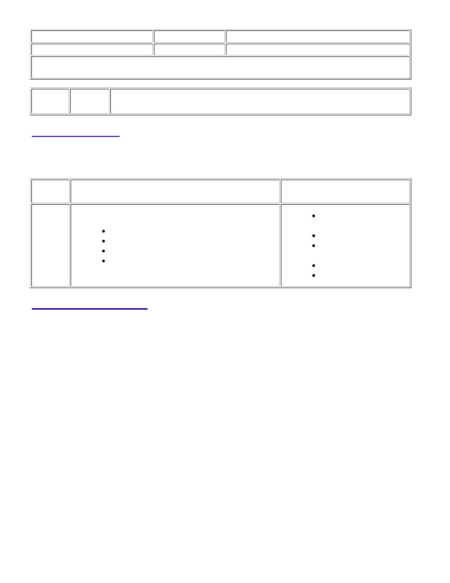
DTC

C1207/37 Malfunction in Park / Neutral Position Switch

DESCRIPTION

The park / neutral position switch signal is sent to the skid control ECU via the CAN communication system.

When there is a malfunction in the CAN communication system, it will be detected by the diagnostic function.

DTC

CODE

DTC DETECTION CONDITION

TROUBLE AREA

C1207/37

When all conditions below are met:

Yaw rate sensor is normal.

G sensor lateral operation is normal.

Vehicle speed is 40 km/h (24.9 mph) or more.

Reversing signal is output from ECM for 1 second

or more.

Park / Neutral position

switch

ECM

CAN communication

system

Harness or connector

Skid control ECU

WIRING DIAGRAM

BRAKE CONTROL: VEHICLE STABILITY CONTROL SYSTEM: C...

INSPECTION PROCEDURE

NOTICE:

When replacing the VSC actuator assembly, perform zero point calibration 


.

PROCEDURE

1.

CHECK CAN COMMUNICATION SYSTEM

(a) Check if a CAN communication system DTC is output 


.

Result

RESULT

PROCEED TO

DTC is not output

A

DTC is output

B

B

GO TO CAN COMMUNICATION SYSTEM

BRAKE CONTROL: VEHICLE STABILITY CONTROL SYSTEM: C...

A

2.

INSPECT PARK / NEUTRAL POSITION SWITCH ASSEMBLY

(a) Disconnect the D35 switch connector.

Standard Resistance:

TESTER CONNECTION

SWITCH CONDITION

SPECIFIED CONDITION

2 (RB) - 6 (PL)

4 (B) - 5 (L)

Shift lever position on P

Below 1 Ω

2 (RB) - 1 (RL)

Shift lever position on R

2 (RB) - 9 (NL)

4 (B) - 5 (L)

Shift lever position on N

2 (RB) - 7 (DL)

Shift lever position on D

Shift lever position on S, "+" and "-"

2 (RB) - 6 (PL)

4 (B) - 5 (L)

Shift lever position not on P

10 kΩ or higher

2 (RB) - 1 (RL)

Shift lever position not on R

2 (RB) - 9 (NL)

4 (B) - 5 (L)

Shift lever position not on N

2 (RB) - 7 (DL)

Shift lever position not on D

Shift lever position not on S, "+" and "-"

NG

REPLACE PARK / NEUTRAL POSITION SWITCH

ASSEMBLY

BRAKE CONTROL: VEHICLE STABILITY CONTROL SYSTEM: C...

OK

OK

3.

CHECK PARK / NEUTRAL POSITION SWITCH ASSEMBLY (POWER SOURCE)

(a) Disconnect the D35 switch connector.

(b) Measure the voltage according to the value(s) in the table below.

Standard Voltage:

TESTER CONNECTION

SWITCH CONDITION

SPECIFIED CONDITION

D35-2 (RB) - Body ground

Ignition switch ON

11 to 14 V

D35-2 (RB) - Body ground

Ignition switch off

Below 1 V

NG

REPAIR OR REPLACE HARNESS OR CONNECTOR

(PARK / NEUTRAL POSITION SWITCH - IGNITION

SWITCH)

4.

CHECK HARNESS AND CONNECTOR (PARK / NEUTRAL POSITION SWITCH - ECM)

BRAKE CONTROL: VEHICLE STABILITY CONTROL SYSTEM: C...


Content   ..  239  240  241  242   ..