Toyota Tundra (2015 year). Manual - part 2287


  Index      Toyota     Toyota Tundra (2015 year) - Service and Repair Manual


Search            copyright infringement  


Content   ..  2285  2286  2287  2288   ..


Toyota Tundra (2015 year). Manual - part 2287


OK

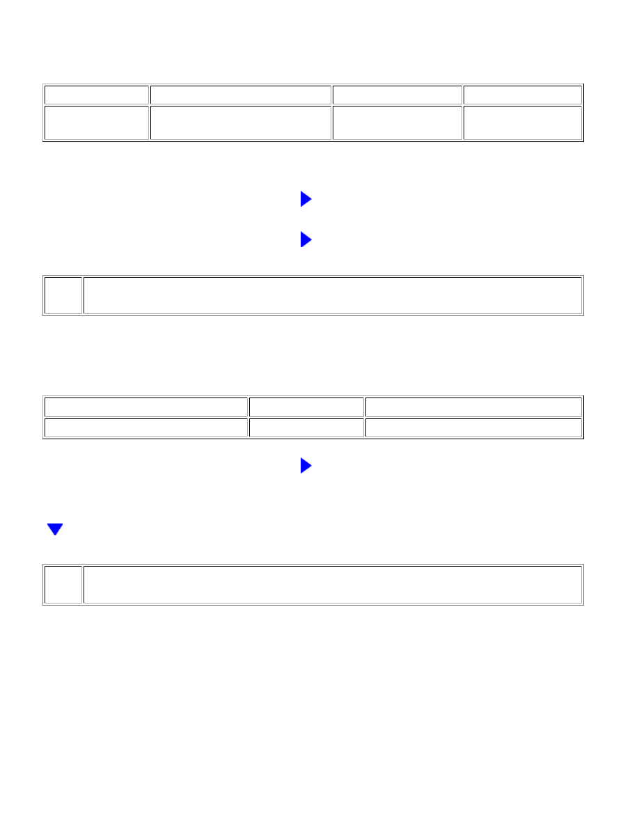
(a) Use the Data List to check if the air conditioning signal is functioning properly.

Engine and ECT

TESTER DISPLAY

MEASUREMENT ITEM / RANGE

NORMAL CONDITION

DIAGNOSTIC NOTE

A/C Signal

A/C switch signal /

ON or OFF

ON: A/C switch ON

OFF: A/C switch OFF

-

OK:

The display is as specified in the normal condition.

NG

GO TO STEP 2

OK

PROCEED TO NEXT CIRCUIT INSPECTION SHOWN

IN PROBLEM SYMPTOMS TABLE

2.

INSPECT FUSE (A/C IG)

(a) Remove the A/C IG fuse from the main body ECU.

(b) Measure the resistance according to the value(s) in the table below.

Standard resistance:

TESTER CONNECTION

CONDITION

SPECIFIED CONDITION

A/C IG fuse

Always

Below 1 Ω

NG

REPLACE FUSE

3.

CHECK HARNESS AND CONNECTOR (ENGINE ROOM RELAY BLOCK - BATTERY)

AIR CONDITIONING: AIR CONDITIONING SYSTEM (for Manual Air...

OK

(a) Remove the magnetic clutch relay (MG CLT) from the engine

room relay block, junction block.

(b) Measure the voltage according to the value(s) in the table

below.

Standard voltage:

TESTER CONNECTION

SWITCH

CONDITION

SPECIFIED

CONDITION

Engine room relay block, junction

block magnetic clutch relay terminal

5 - Body ground

Ignition switch

ON

11 to 14 V

Ignition switch

off

Below 1 V

Engine room relay block, junction

block magnetic clutch relay terminal

1 - Body ground

Ignition switch

ON

11 to 14 V

Ignition switch

off

Below 1 V

NG

REPAIR OR REPLACE HARNESS OR CONNECTOR

4.

INSPECT MAGNETIC CLUTCH RELAY (MG CLT)

(a) Remove the magnetic clutch relay from the engine room

relay block, junction block.

(b) Measure the resistance according to the value(s) in the table

below.

Standard resistance:

TESTER

CONNECTION

CONDITION

SPECIFIED

CONDITION

3 - 5

When battery voltage is not

applied between terminals 1 and

2

10 kΩ or higher

When battery voltage is applied

to terminals 1 and 2

Below 1 Ω

AIR CONDITIONING: AIR CONDITIONING SYSTEM (for Manual Air...

OK

OK

NG

REPLACE MAGNETIC CLUTCH RELAY

5.

CHECK HARNESS AND CONNECTOR (AIR CONDITIONING AMPLIFIER - BATTERY)

(a) Disconnect the J19 air conditioning amplifier connector.

(b) Measure the voltage according to the value(s) in the table

below.

Standard voltage:

TESTER CONNECTION

SWITCH

CONDITION

SPECIFIED

CONDITION

J19-20 (MGC) - Body

ground

Ignition switch OFF

Below 1 V

Ignition switch ON

11 to 14 V

NG

REPAIR OR REPLACE HARNESS OR CONNECTOR

6.

CHECK AIR CONDITIONING AMPLIFIER (MGC VOLTAGE)

(a) Reconnect the J19 air conditioning amplifier connector.

(b) Measure the voltage according to the value(s) in the table

below.

Standard voltage:

TESTER CONNECTION

SWITCH

CONDITION

SPECIFIED

CONDITION

J19-20 (MGC) - Body

ground

Engine is running

Blower switch LO

A/C switch ON

Below 1 V

AIR CONDITIONING: AIR CONDITIONING SYSTEM (for Manual Air...

OK

OK

TESTER CONNECTION

SWITCH

CONDITION

SPECIFIED

CONDITION

Engine is running

Blower switch LO

A/C switch OFF

11 to 14 V

NG

REPLACE AIR CONDITIONING AMPLIFIER

7.

INSPECT AIR CONDITIONING COMPRESSOR (COMPRESSOR HARNESS)

(a) Disconnect the D60 air conditioning compressor connector.

(b) Disconnect the magnetic clutch connector.

(c) Measure the resistance according to the value(s) in the table

below.

Standard resistance:

TESTER CONNECTION

CONDITION

SPECIFIED CONDITION

3 (MG+) - 1

Always

Below 1 Ω

3 (MG+) or 1 - Body ground

Always

10 kΩ or higher

NG

REPAIR AIR CONDITIONING COMPRESSOR

8.

INSPECT MAGNETIC CLUTCH

AIR CONDITIONING: AIR CONDITIONING SYSTEM (for Manual Air...


Content   ..  2285  2286  2287  2288   ..