Content .. 2244 2245 2246 2247 ..
Toyota Tundra (2015 year). Manual - part 2246
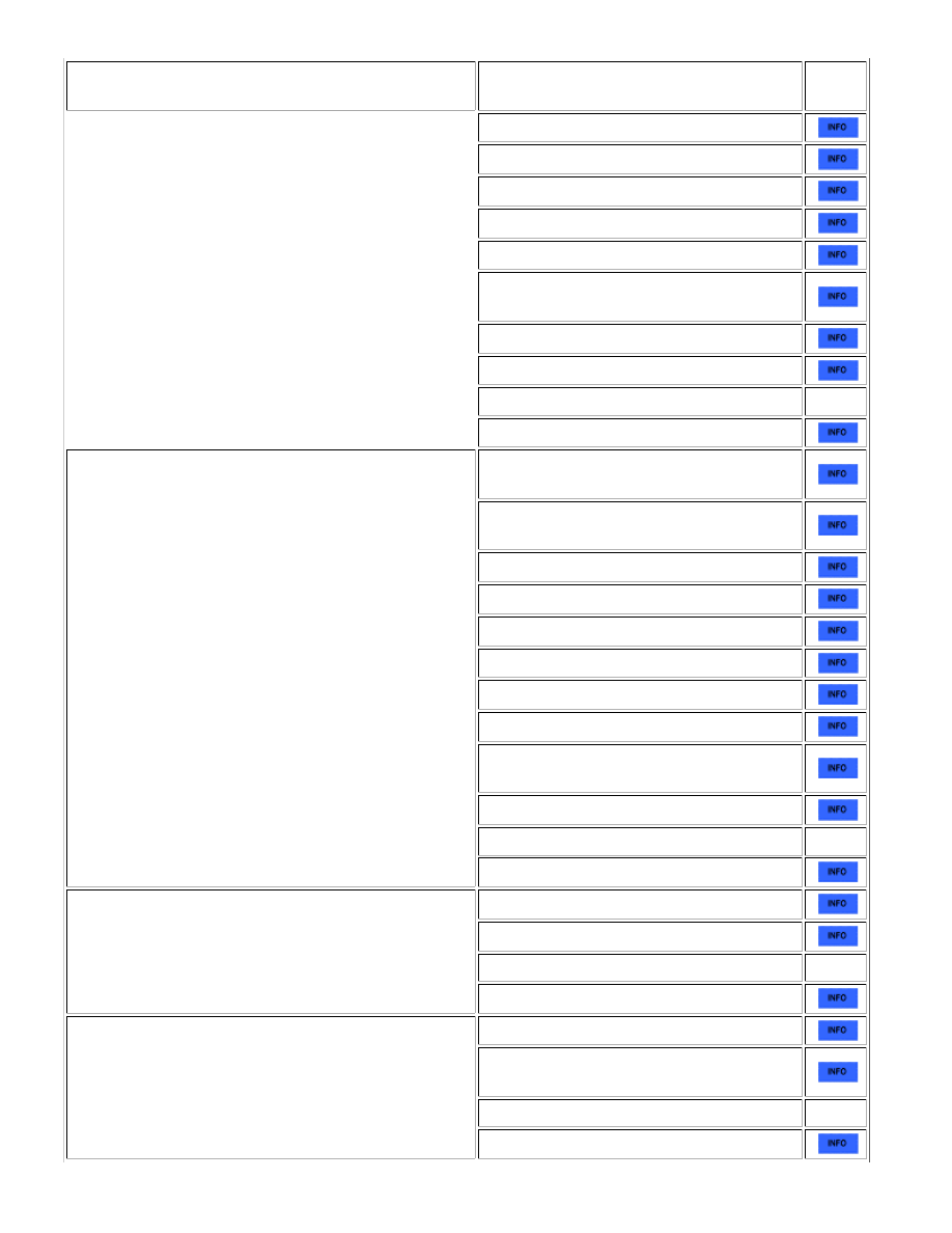
SYMPTOM
SUSPECTED AREA
SEE
PAGE
Cool air bypass servo motor circuit
Radiator unit sub-assembly (for 1UR-FE)
Radiator unit sub-assembly (for 3UR-FE)
Radiator unit sub-assembly (for 3UR-FBE)
Expansion valve
No. 1 damper servo sub-assembly (air mix
servo motor [for driver side])
Air mix servo motor (for passenger side)
Cool Air Bypass Servo Motor
Air conditioning harness
-
Air conditioning amplifier
Temperature Control: No temperature control (only
Max. cool or Max. warm)
Air mix damper control servo motor circuit
(for Driver Side)
Air mix damper control servo motor circuit
(for Passenger Side)
Room temperature sensor circuit
Ambient temperature sensor circuit
Evaporator temperature sensor circuit
Solar sensor circuit (for Driver Side)
Solar sensor circuit (for Passenger Side)
Air conditioning control assembly
No. 1 damper servo sub-assembly (air mix
servo motor [for driver side])
Air mix servo motor (for passenger side)
Air conditioning harness
-
Air conditioning amplifier
No air inlet control
Air inlet control servo motor circuit
Air inlet servo motor
Air conditioning harness
-
Air conditioning amplifier
No air flow mode control
Air outlet control servo motor circuit
No. 1 damper servo sub-assembly (air outlet
servo motor)
Air conditioning harness
-
Air conditioning amplifier
AIR CONDITIONING: AIR CONDITIONING SYSTEM (for Automatic A...