Toyota Tundra (2015 year). Manual - part 2051


  Index      Toyota     Toyota Tundra (2015 year) - Service and Repair Manual


Search            copyright infringement  


Content   ..  2049  2050  2051  2052   ..


Toyota Tundra (2015 year). Manual - part 2051


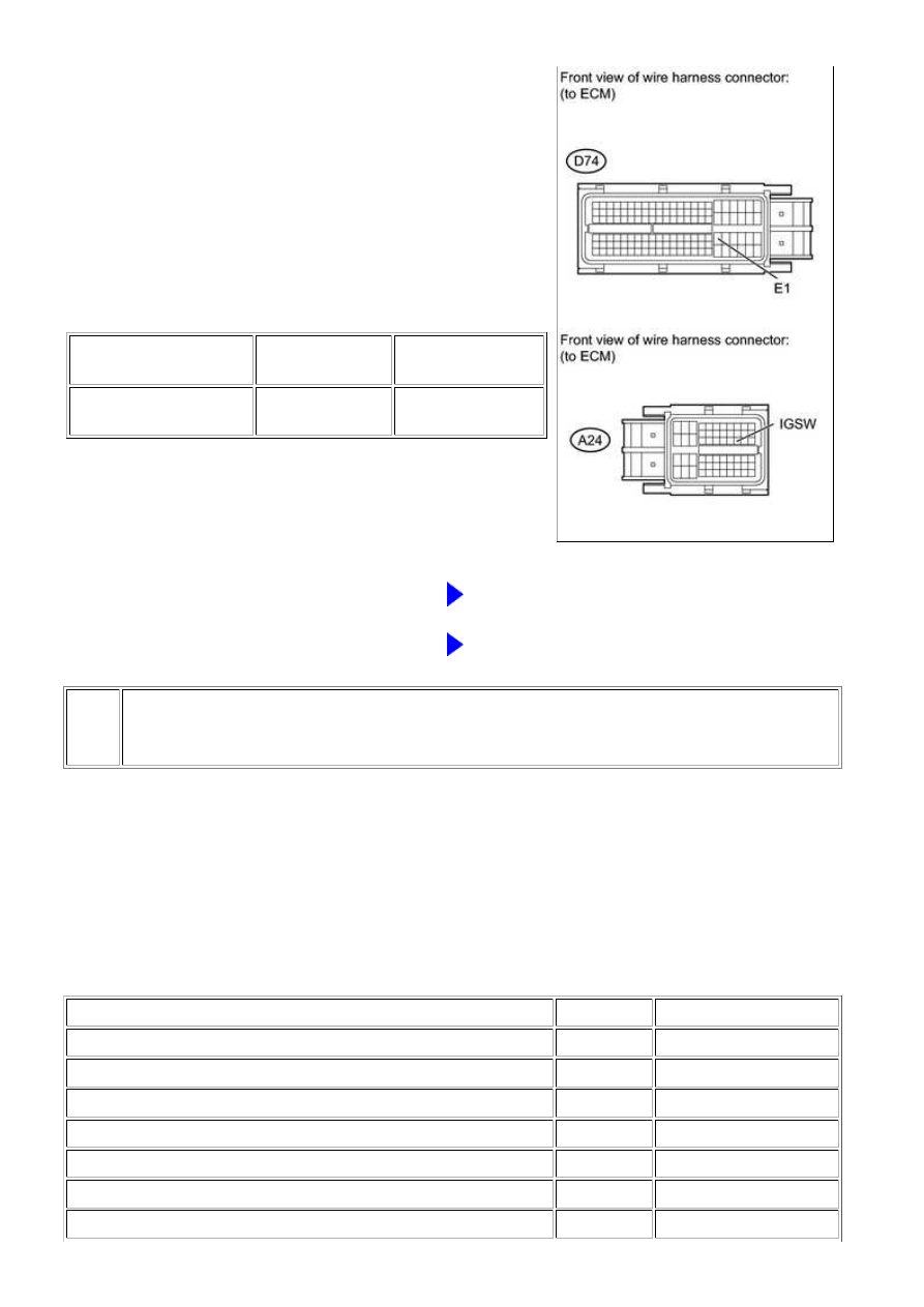
(a) Disconnect the A24 and D74 ECM connectors.

(b) Turn the ignition switch to ON.

(c) Measure the voltage according to the value(s) in the

table below.

Standard voltage:

TESTER CONNECTION

SWITCH

CONDITION

SPECIFIED

CONDITION

A24-28 (IGSW) - D74-81

(E1)

Ignition switch ON

11 to 14 V

NG

GO TO STEP 5

OK

REPLACE ECM

5.

CHECK HARNESS AND CONNECTOR (RELAY BLOCK - ECM, IGNITION SWITCH,
BATTERY AND BODY GROUND)

(a) Disconnect the A24 ECM connector.

(b) Disconnect the J9 ignition switch connector.

(c) Disconnect the cable from the battery positive (+) terminal.

(d) Remove the AM2 fuse and integration relay.

(e) Measure the resistance according to the value(s) in the table below.

Standard resistance:

TESTER CONNECTION

CONDITION

SPECIFIED CONDITION

A24-28 (IGSW) - 1B-8

Always

Below 1 Ω

1B-7 - Body ground

Always

Below 1 Ω

Positive (+) battery cable - 1C-1

Always

Below 1 Ω

Positive (+) battery cable - AM2 fuse terminal 1

Always

Below 1 Ω

J9-5 (AM2) - AM2 fuse terminal 2

Always

Below 1 Ω

J9-6 (IG2) - 1B-6

Always

Below 1 Ω

A24-28 (IGSW) or 1B-8 - Body ground

Always

10 kΩ or higher

3UR-FE ENGINE CONTROL SYSTEM: SFI SYSTEM: ECM Power S...

OK

OK

TESTER CONNECTION

CONDITION

SPECIFIED CONDITION

Positive (+) battery cable or AM2 fuse terminal 1 - Body ground

Always

10 kΩ or higher

Positive (+) battery cable or 1C-1 - Body ground

Always

10 kΩ or higher

J9-5 (AM2) or AM2 fuse terminal 2 - Body ground

Always

10 kΩ or higher

J9-6 (IG2) or 1B-6 - Body ground

Always

10 kΩ or higher

NG

REPAIR OR REPLACE HARNESS OR CONNECTOR

6.

INSPECT IGNITION SWITCH

(a) Inspect the ignition switch 


.

NG

REPLACE IGNITION SWITCH

7.

CHECK HARNESS AND CONNECTOR (INTEGRATION RELAY - ECM, BATTERY AND
BODY GROUND)

(a) Disconnect the A24 ECM connector.

(b) Disconnect the cable from the battery positive terminal.

(c) Remove the integration relay from the engine room relay block.

(d) Disconnect the integration relay connector.

(e) Measure the resistance according to the value(s) in the table below.

Standard resistance:

TESTER CONNECTION

CONDITION

SPECIFIED CONDITION

A24-3 (+B) - 1B-4

Always

Below 1 Ω

A24-2 (+B2) - 1B-4

Always

Below 1 Ω

A24-34 (MREL) - 1B-2

Always

Below 1 Ω

1C-1 - Positive (+) battery cable

Always

Below 1 Ω

1B-3 - Body ground

Always

Below 1 Ω

A24-3 (+B) or 1B-4 - Body ground

Always

10 kΩ or higher

A24-2 (+B2) or 1B-4 - Body ground

Always

10 kΩ or higher

3UR-FE ENGINE CONTROL SYSTEM: SFI SYSTEM: ECM Power S...

TESTER CONNECTION

CONDITION

SPECIFIED CONDITION

A24-34 (MREL) or 1B-2 - Body ground

Always

10 kΩ or higher

1C-1 or Positive (+) battery cable - Body ground

Always

10 kΩ or higher

NG

REPAIR OR REPLACE HARNESS OR CONNECTOR

OK

REPAIR OR REPLACE ENGINE ROOM RELAY

BLOCK

3UR-FE ENGINE CONTROL SYSTEM: SFI SYSTEM: ECM Power S...

Last Modified: 9-16-2014

6.6 J

Doc ID: RM000001D6V0U3X

Model Year: 2015

Model: Tundra

Prod Date Range: [08/2014 -           ]

Title: 3UR-FE ENGINE CONTROL SYSTEM: SFI SYSTEM: VC Output Circuit; 2015 MY Tundra [08/2014 -        ]

VC Output Circuit

DESCRIPTION

The ECM constantly generates 5 V power from the battery voltages supplied to the +B (BATT) terminal to

operate the microprocessor. The ECM also provides this power to the sensors through the VC output circuit.

When the VC circuit is short-circuited, the microprocessor in the ECM and sensors that are supplied with power

through the VC circuit are inactivated because the power is not supplied from the VC circuit. Under this

condition, the system does not start up and the MIL does not illuminate even if the system malfunctions.

HINT:

Under normal conditions, the MIL is illuminated for several seconds when the ignition switch is first

turned to ON. The MIL goes off when the engine is started.

WIRING DIAGRAM

3UR-FE ENGINE CONTROL SYSTEM: SFI SYSTEM: VC Output Cir...


Content   ..  2049  2050  2051  2052   ..