Toyota Tundra (2015 year). Manual - part 2025


  Index      Toyota     Toyota Tundra (2015 year) - Service and Repair Manual


Search            copyright infringement  


Content   ..  2023  2024  2025  2026   ..


Toyota Tundra (2015 year). Manual - part 2025


NOTICE:

1. 

Turn the ignition switch to ON and turn the Techstream on.

2. 

Clear DTCs (even if no DTCs are stored, perform the clear DTC operation).

3. 

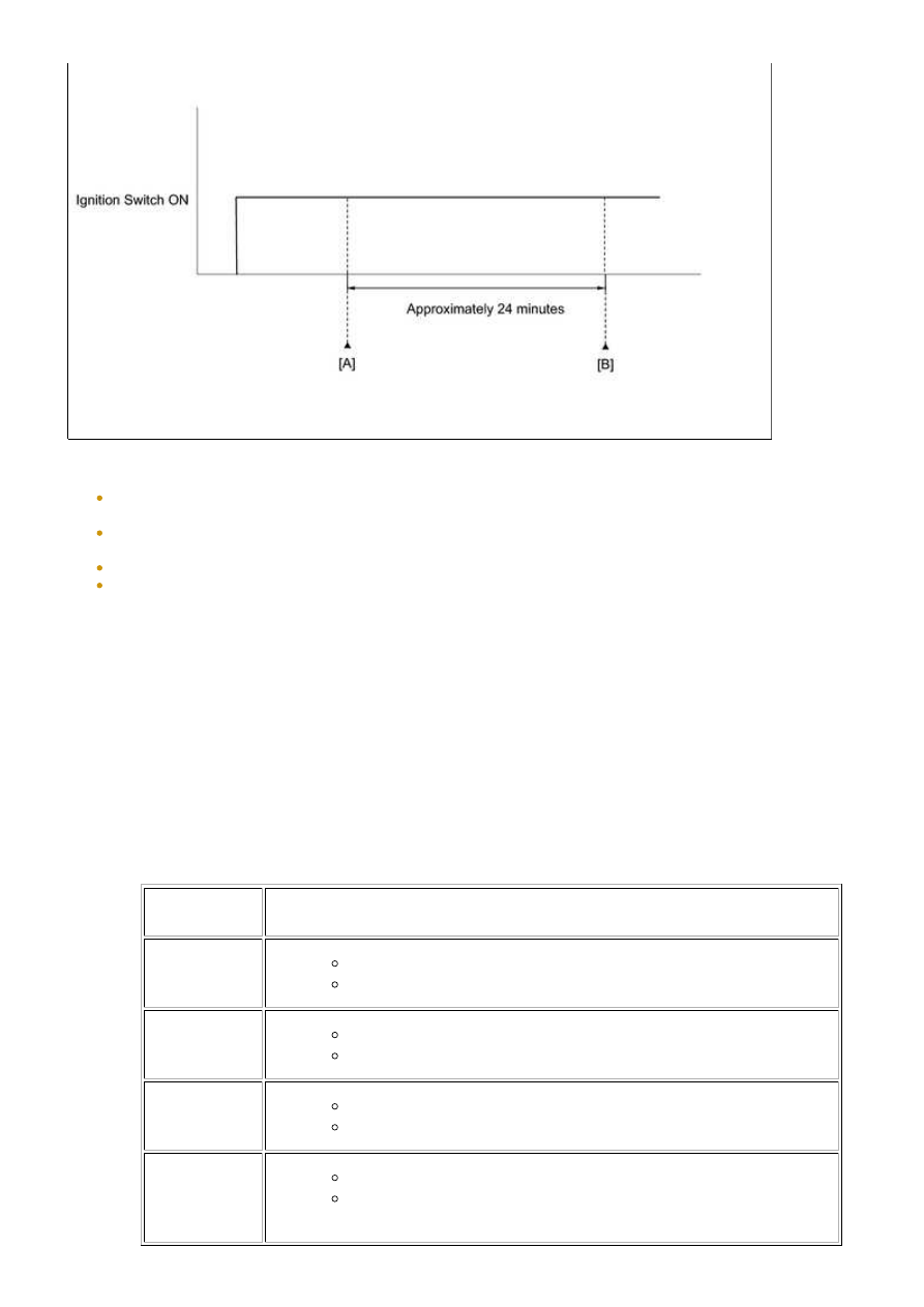
Turn the ignition switch off and wait for at least 30 seconds.

4. 

Turn the ignition switch to ON and turn the Techstream on [A].

5. 

Enter the following menu items: Powertrain / Engine and ECT / Utility / Evaporative System Check

/ Automatic Mode.

6. 

After the EVAP SYSTEM CHECK is completed, check for All Readiness by entering the following

menus: Powertrain / Engine and ECT / Utility / All Readiness.

7. 

Input the DTC: P2420.

8. 

Check the DTC judgment result [B].

TESTER

DISPLAY

DESCRIPTION

NORMAL

DTC judgment completed

System normal

ABNORMAL

DTC judgment completed

System abnormal

INCOMPLETE

DTC judgment not completed

Perform driving pattern after confirming DTC enabling conditions

N/A

Unable to perform DTC judgment

9. 

3UR-FE ENGINE CONTROL SYSTEM: SFI SYSTEM: P2420; Evapor...

HINT:

If the judgment result shows ABNORMAL, the system has a malfunction.

If the test result is INCOMPLETE or N/A and no pending DTC is output, perform a universal trip and

check for permanent DTCs 


.

HINT:

If a permanent DTC is output, the system is malfunctioning.
If no permanent DTC is output, the system is normal.

10. 

3UR-FE ENGINE CONTROL SYSTEM: SFI SYSTEM: P2420; Evapor...

Last Modified: 9-16-2014

6.6 C

Doc ID: RM0000013HB04SX

Model Year: 2015

Model: Tundra

Prod Date Range: [08/2014 -           ]

Title: 3UR-FE ENGINE CONTROL SYSTEM: SFI SYSTEM: P2431-P2433,P2436-P2438; Secondary Air Injection

System Air Flow / Pressure Sensor Circuit Range / Performance Bank1; 2015 MY Tundra [08/2014 -        ]

DTC

P2431

Secondary Air Injection System Air Flow / Pressure Sensor Circuit Range /

Performance Bank1

DTC

P2432

Secondary Air Injection System Air Flow / Pressure Sensor Circuit Low

Bank1

DTC

P2433

Secondary Air Injection System Air Flow / Pressure Sensor Circuit High

Bank1

DTC

P2436

Secondary Air Injection System Air Flow / Pressure Sensor Circuit Range /

Performance Bank 2

DTC

P2437

Secondary Air Injection System Air Flow / Pressure Sensor Circuit Low Bank

2

DTC

P2438

Secondary Air Injection System Air Flow / Pressure Sensor Circuit High Bank

2

DESCRIPTION

The AID drives the ASV and the air pump according to command signals transmitted by the ECM. The pressure

sensor detects the pressure in the secondary air passage when the AIR system is ON and OFF, and transmits a

pressure signal to the ECM.

The AID is not only equipped to drive the pump and valve, but also with a diagnosis function to detect

malfunctions in the AIR system circuit.

HINT:

As a large current is required to drive the air pump and ASV, an AID is installed to this system.

3UR-FE ENGINE CONTROL SYSTEM: SFI SYSTEM: P2431-P2433...

DTC

CODE

DTC DETECTION CONDITION

TROUBLE AREA

P2431

P2436

Pressure sensor indicates less than 45.6 kPa (342 mmHg), or

more than 135 kPa (1013 mmHg) (2 trip detection logic)

Pressure sensor

Open or short in

pressure sensor circuit

ECM

P2432

P2437

Pressure sensor

Open or short in

pressure sensor circuit

ECM

P2433

P2438

Pressure sensor

Open or short in

pressure sensor circuit

ECM

MONITOR DESCRIPTION

3UR-FE ENGINE CONTROL SYSTEM: SFI SYSTEM: P2431-P2433...


Content   ..  2023  2024  2025  2026   ..