Toyota Tundra (2015 year). Manual - part 1967


  Index      Toyota     Toyota Tundra (2015 year) - Service and Repair Manual


Search            copyright infringement  


Content   ..  1965  1966  1967  1968   ..


Toyota Tundra (2015 year). Manual - part 1967


3.

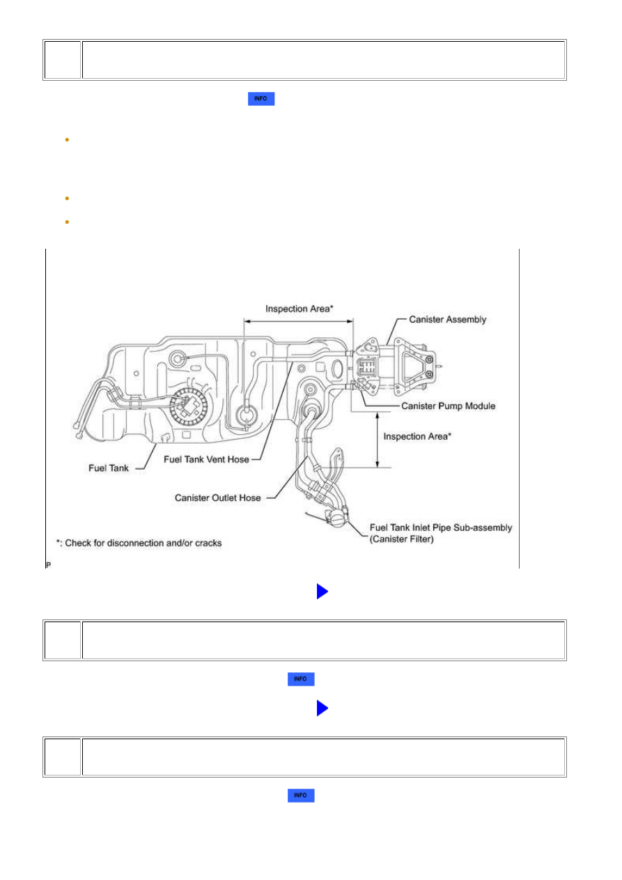
REPLACE CANISTER PUMP MODULE

(a) Replace the canister pump module 


.

NOTICE:

When replacing canister pump module, check the canister pump module interior, canister interior and
related pipes for water, fuel and other liquids. If liquids are present, check for disconnections and/or
cracks in the following: 1) the pipe from the air inlet port to the canister pump module; 2) the canister
filter; and 3) the fuel tank vent hose. If liquids are present in canister interior, replace canister and
canister pump module together (replace canister assembly).
Check for filter blockage in the canister assembly. If the charcoal filter inside the canister assembly is
clogged, replace canister and canister pump module together (replace canister assembly).
Check for filter blockage in the canister filter. If the canister filter has blockages, replace the canister
filter.

NEXT

GO TO STEP 6

4.

REPLACE AIR SWITCHING VALVE (BANK 1)

(a) Replace the air switching valve for bank 1 


.

NEXT

GO TO STEP 6

5.

REPLACE AIR SWITCHING VALVE (BANK 2)

(a) Replace the air switching valve for bank 2 


.

3UR-FE ENGINE CONTROL SYSTEM: SFI SYSTEM: P106B; Evapo...

NEXT

6.

CONFIRM WHETHER MALFUNCTION HAS BEEN SUCCESSFULLY REPAIRED

(a) Connect the Techstream to the DLC3.

(b) Turn the ignition switch to ON and turn the Techstream on.

(c) Enter the following menus: Powertrain / Engine and ECT / Data List / Vapor Pressure Pump, Air

pump pressure (absolute) and Air Pump2 Pressure (Absolute).

(d) Confirm that the difference between Vapor Pressure Pump and Air pump pressure (Absolute),

and the difference between Vapor Pressure Pump and Air Pump2 Pressure (Absolute) are 3.5
kPa (+/- 26.25 mmHg) or less.

NEXT

END

3UR-FE ENGINE CONTROL SYSTEM: SFI SYSTEM: P106B; Evapo...

Last Modified: 9-16-2014

6.6 C

Doc ID: RM000000TMH05TX

Model Year: 2015

Model: Tundra

Prod Date Range: [08/2014 -           ]

Title: 3UR-FE ENGINE CONTROL SYSTEM: SFI SYSTEM: P1340,P1342,P1343; Camshaft Position Sensor "A"

(Bank 1 Sensor 2); 2015 MY Tundra [08/2014 -        ]

DTC

P1340

Camshaft Position Sensor "A" (Bank 1 Sensor 2)

DTC

P1342

Camshaft Position Sensor "A" Low Input (MRE)

DTC

P1343

Camshaft Position Sensor "A" High Input (MRE)

DESCRIPTION

changes between the protrusion on the teeth and MRE. The change affects the magnetic field and results in

crankshaft position sensor generates 34 signals at every engine revolution. The ECM detects the standard

crankshaft angle based on the G signal, and the actual crankshaft angle and engine speed by the NE signal.

DTC

CODE

DTC DETECTION CONDITION

TROUBLE AREA

P1340

No camshaft position sensor signal to ECM during

cranking (2 trip detection logic)

Open or short in camshaft

position sensor circuit

Camshaft position sensor

Camshaft timing plate LH

ECM

No camshaft position sensor signal to ECM with

engine speed 600 rpm or more

P1342

(1 trip detection logic)

P1343

(1 trip detection logic)

MONITOR DESCRIPTION

changes between the protrusion on the teeth and the MRE. The change affects the magnetic field and results in

actual crankshaft angle and engine speed by the NE signal.

MONITOR STRATEGY

Related DTCs

P1340: Camshaft position sensor verify pulse input

3UR-FE ENGINE CONTROL SYSTEM: SFI SYSTEM: P1340,P1342...

P1340: Camshaft position / Crankshaft position misalignment

P1342: Camshaft position sensor range check (low voltage)

P1343: Camshaft position sensor range check (high voltage)

Required Sensors/Components

(Main)

Camshaft position sensor

Required Sensors/Components

(Related)

Crankshaft position sensor, Engine speed sensor

Duration

4 seconds:

P1340 camshaft position sensor verify pulse input

P1342: Camshaft position sensor range check (low voltage)

P1343: Camshaft position sensor range check (high voltage)

5 seconds:

P1340 camshaft position / crankshaft position misalignment

MIL Operation

2 driving cycles: P1340 camshaft position sensor verify pulse input

Immediate: P1340 camshaft position / crankshaft position misalignment

and P1342, P1343 camshaft position sensor range check

TYPICAL ENABLING CONDITIONS

P1340 camshaft position sensor verify pulse input:

Monitor runs whenever following DTCs not present

None

Starter

ON (Not starter ON again)

Minimal battery voltage while starter ON

Less than 11 V

P1340 camshaft position / crankshaft position misalignment:

Monitor runs whenever following DTCs not present

P0342, P0343 (VVT sensor)

P1342, P1343 (Camshaft position sensor)

Engine RPM

600 rpm or more

Starter

OFF

Camshaft position sensor range check fail (P1342, P1343)

Not detected

Camshaft position sensor range

0.3 to 4.7 V

P1342, P1343 camshaft position sensor range check:

Monitor runs whenever following DTCs not present

P0340, P1340 (Camshaft position sensor)

Time after ignition switch off to ON

2 seconds or more

Camshaft position sensor verify pulse input fail (P1340)

Not detected

Battery voltage

8 V or more

Starter

OFF

TYPICAL MALFUNCTION THRESHOLDS

P1340 camshaft position sensor verify pulse input:

3UR-FE ENGINE CONTROL SYSTEM: SFI SYSTEM: P1340,P1342...


Content   ..  1965  1966  1967  1968   ..