Toyota Tundra (2015 year). Manual - part 1682


  Index      Toyota     Toyota Tundra (2015 year) - Service and Repair Manual


Search            copyright infringement  


Content   ..  1680  1681  1682  1683   ..


Toyota Tundra (2015 year). Manual - part 1682
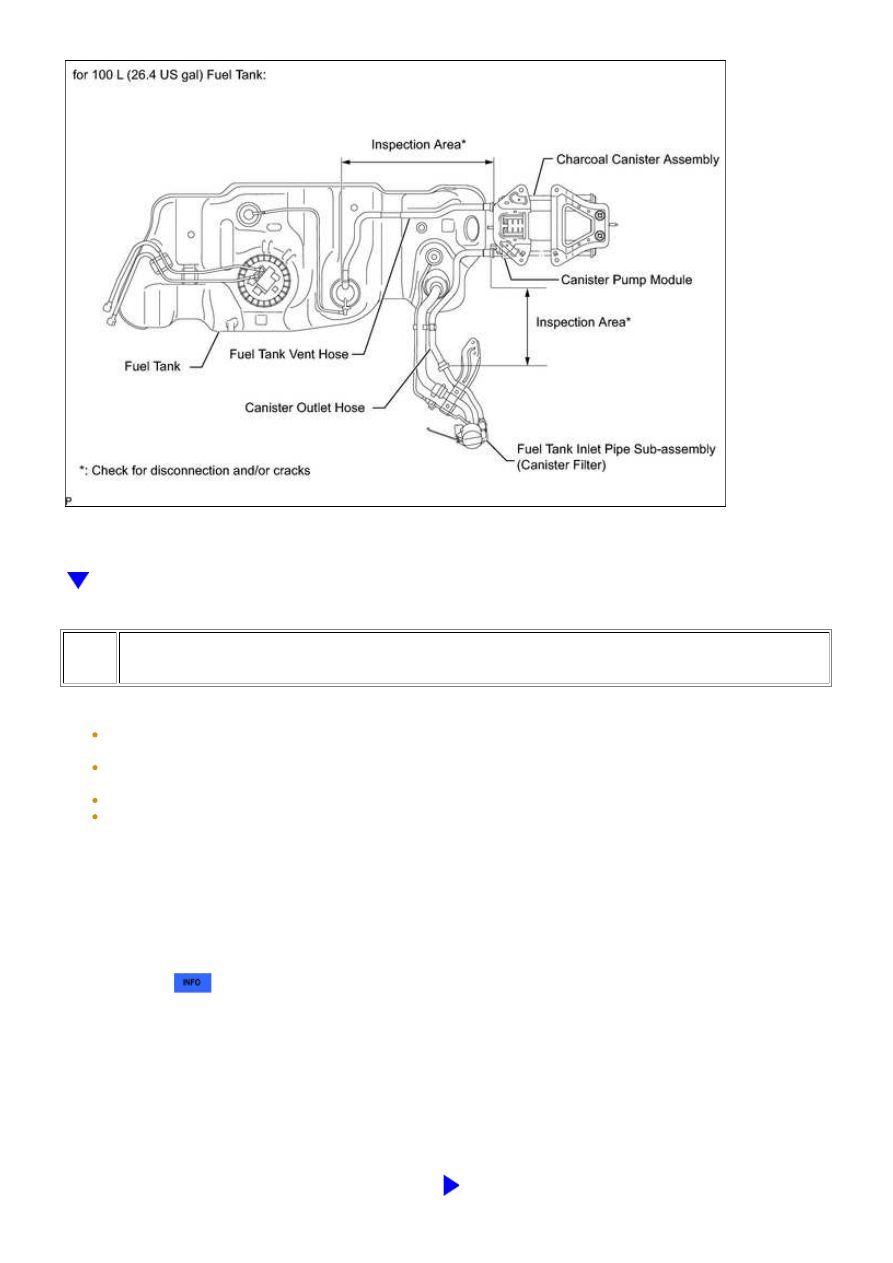


NEXT

51.

PERFORM EVAP SYSTEM CHECK (AUTOMATIC MODE)

NOTICE:

(b) Turn the ignition switch to ON.

(c) Turn the Techstream on.

(d) Clear DTCs 


.

(e) Enter the following menus: Powertrain / Engine and ECT / Utility / Evaporative System Check /

Automatic Mode.

(f) After the Evaporative System Check is completed, check for pending DTCs by entering the following

menus: Powertrain / Engine and ECT / Trouble Codes

HINT:

If no pending DTCs are found, the repair has been successfully completed.

NEXT

END

3UR-FBE ENGINE CONTROL SYSTEM: SFI SYSTEM: EVAP System...

3UR-FBE ENGINE CONTROL SYSTEM: SFI SYSTEM: EVAP System...

Last Modified: 9-16-2014

6.6 J

Doc ID: RM000001DN80AXX

Model Year: 2015

Model: Tundra

Prod Date Range: [08/2014 -           ]

Title: 3UR-FBE ENGINE CONTROL SYSTEM: SFI SYSTEM: ECM Power Source Circuit; 2015 MY Tundra

[08/2014 -        ]

ECM Power Source Circuit

DESCRIPTION

INSPECTION PROCEDURE

PROCEDURE

1.

INSPECT FUSES (AM2, IG2 MAIN, EFI NO. 1, IGN)

3UR-FBE ENGINE CONTROL SYSTEM: SFI SYSTEM: ECM Power...

OK

(a) Remove the AM2 fuse, IG2 MAIN fuse, EFI NO. 1 fuse

and IGN fuse from the engine room relay block.

(b) Measure the resistance according to the value(s) in the

table below.

Standard resistance:

TESTER CONNECTION

CONDITION

SPECIFIED CONDITION

AM2 fuse

Always

Below 1 Ω

IG2 MAIN fuse

Always

Below 1 Ω

EFI NO. 1 fuse

Always

Below 1 Ω

IGN fuse

Always

Below 1 Ω

NG

CHECK FOR SHORT IN ALL HARNESSES AND

CONNECTORS CONNECTED TO FUSE AND

REPLACE FUSE

2.

INSPECT INTEGRATION RELAY (IG2, EFI)

(a) Remove the integration relay from the engine room

relay block.

(b) Measure the resistance according to the value(s) in the

table below.

Standard resistance:

TESTER

CONNECTION

CONDITION

SPECIFIED

CONDITION

1C-1 - 1B-8

When no battery voltage is

applied to terminals 1B-6 and

1B-7

10 kΩ or higher

1C-1 - 1B-8

When battery voltage is

applied to terminals 1B-6 and

1B-7

Below 1 Ω

1C-1 - 1B-4

When no battery voltage is

applied to terminals 1B-2 and

1B-3

10 kΩ or higher

3UR-FBE ENGINE CONTROL SYSTEM: SFI SYSTEM: ECM Power...


Content   ..  1680  1681  1682  1683   ..