Index Toyota Toyota Tundra (2015 year) - Service and Repair Manual
Search copyright infringement
Content .. 1554 1555 1556 1557 ..
Toyota Tundra (2015 year). Manual - part 1556
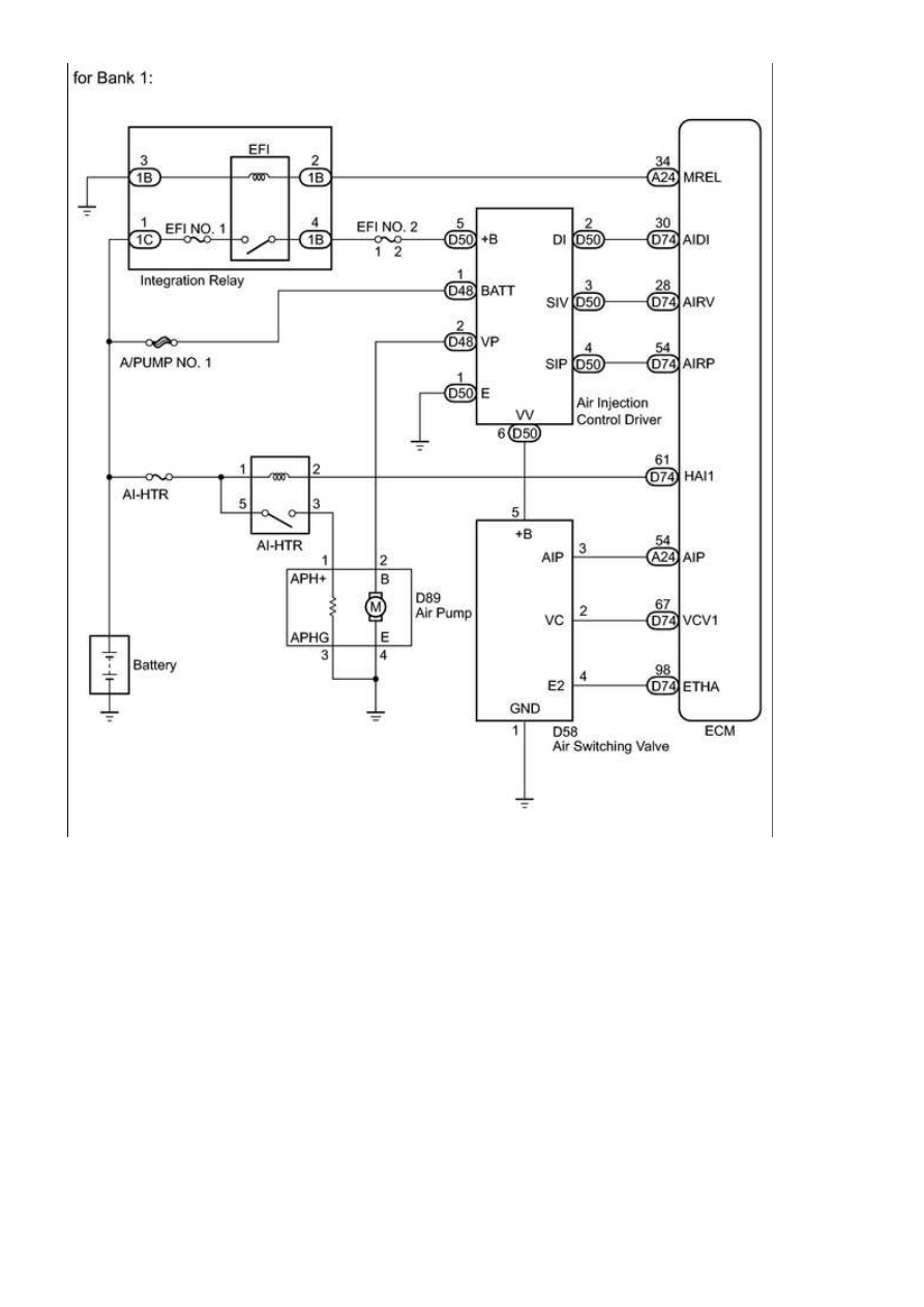
3UR-FBE ENGINE CONTROL SYSTEM: SFI SYSTEM: P0412,P0415...