Content .. 1505 1506 1507 1508 ..
Toyota Tundra (2015 year). Manual - part 1507
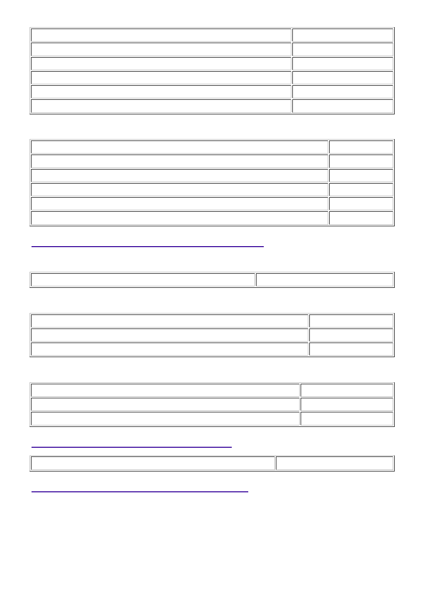
Monitor runs whenever following DTCs not stored
None
Battery voltage
10.5 V or more
Time after heater ON
5 seconds or more
Active heater OFF control
Not operating
Active heater ON control
Not operating
Heater output duty
More than 0%
P101D and P103D
Monitor runs whenever following DTCs not stored
None
Battery voltage
10.5 V or more
Heater output duty cycle
Less than 60%
Active heater OFF control
Not operating
Active heater ON control
Not operating
Air fuel ratio sensor heater range check low current failure (P0031, P0051)
Not detected
TYPICAL MALFUNCTION THRESHOLDS
P0031 and P0051
A/F sensor heater current
Less than 0.8 A
P0032 and P0052
Command to heater output
ON
Heater current detected by heater monitor IC
14 A or more
P101D and P103D
Heater OFF current
More than 11 A
Heater current detected by heater monitor IC
14 A or more
COMPONENT OPERATING RANGE
A/F sensor heater current
0.9 to 9.9 A
CONFIRMATION DRIVING PATTERN
3UR-FBE ENGINE CONTROL SYSTEM: SFI SYSTEM: P0031,P003...