Toyota Tundra (2015 year). Manual - part 1416


  Index      Toyota     Toyota Tundra (2015 year) - Service and Repair Manual


Search            copyright infringement  


Content   ..  1414  1415  1416  1417   ..


Toyota Tundra (2015 year). Manual - part 1416


Seal packing:

Toyota Genuine Seal Packing Black, Three Bond 1207B or equivalent

Text in Illustration

Seal Packing

NOTICE:

Remove any oil from the contact surface.
Install the cylinder head cover sub-assembly LH within 3 minutes and tighten the bolts within 15 minutes
after applying seal packing.

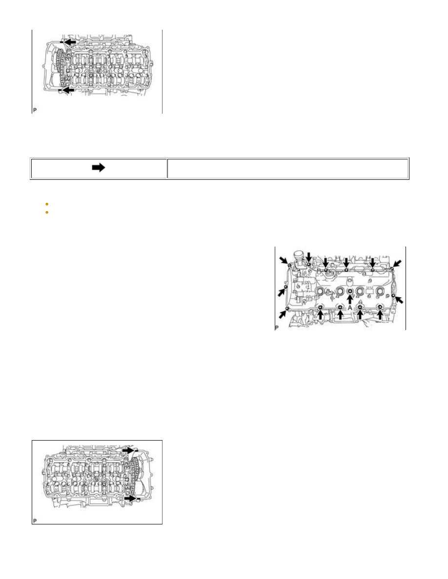
(d) Install the cylinder head cover sub-assembly LH and a new seal

washer with the 14 bolts.

Torque:

for bolt A -

21 N·m {214 kgf·cm, 15ft·lbf}

except bolt A -

12 N·m {122 kgf·cm, 9ft·lbf}

NOTICE:

Do not start the engine for at least 2 hours after the installation.

5. INSTALL CYLINDER HEAD COVER SUB-ASSEMBLY RH

(a) Install 5 new gaskets to the No. 1 camshaft bearing cap and No. 3 camshaft bearing cap.

(b) Install the cylinder head cover gasket RH to the cylinder head cover sub-assembly RH.

NOTICE:

Remove any oil from the contact surface.

(c) Apply seal packing as shown in the illustration.

Seal packing:

Toyota Genuine Seal Packing Black, Three Bond 1207B or equivalent

1UR-FE LUBRICATION: OIL PUMP: INSTALLATION; 2015 MY Tun...

Text in Illustration

Seal Packing

NOTICE:

Remove any oil from the contact surface.
Install the cylinder head cover sub-assembly RH within 3 minutes and tighten the bolts within 15 minutes
after applying seal packing.

(d) Install the cylinder head cover sub-assembly RH and a new seal

washer with the 14 bolts.

Torque:

for bolt A -

21 N·m {214 kgf·cm, 15ft·lbf}

except bolt A -

12 N·m {122 kgf·cm, 9ft·lbf}

NOTICE:

Do not start the engine for at least 2 hours after the installation.

6. INSTALL IGNITION COIL ASSEMBLY

(a) Install the 8 ignition coils with the 8 bolts.

Torque:

10 N·m {102 kgf·cm, 7ft·lbf}

7. CONNECT NO. 3 AIR TUBE

(a) Install a new gasket to the No. 3 air tube.

(b) Connect the No. 3 air tube with the 2 nuts and bolt.

Torque:

10 N·m {102 kgf·cm, 7ft·lbf}

Text in Illustration

*1

No. 3 Air Tube

*2

Exhaust Manifold

*a

Claw

NOTICE:

Make sure the gasket's claws are not caught between the No. 3

air tube and exhaust manifold.

(c) Install the wire harness clamp bracket with the bolt to the cylinder head cover sub-assembly RH.

Torque:

8.0 N·m {82 kgf·cm, 71in·lbf}

8. CONNECT NO. 4 AIR TUBE

(a) Install a new gasket to the No. 4 air tube.

1UR-FE LUBRICATION: OIL PUMP: INSTALLATION; 2015 MY Tun...

(b) Connect the No. 4 air tube with the 2 nuts and bolt.

Torque:

10 N·m {102 kgf·cm, 7ft·lbf}

Text in Illustration

*1

No. 4 Air Tube

*2

Exhaust Manifold

*a

Claw

NOTICE:

Make sure the gasket's claws are not caught between the No. 4

air tube and exhaust manifold.

(c) Install the wire harness clamp bracket with the bolt to the cylinder head cover sub-assembly LH.

Torque:

8.0 N·m {82 kgf·cm, 71in·lbf}

9. INSTALL CRANKSHAFT PULLEY

Text in Illustration

*a

Hold

*b

Turn

(b) Using SST, install the crankshaft pulley set bolt.

SST: 09213-70011

SST: 09330-00021

Torque:

300 N·m {3059 kgf·cm, 221ft·lbf}

10. INSTALL NO. 1 IDLER PULLEY SUB-ASSEMBLY

(a) Install the No. 1 idler pulley sub-assembly to the timing chain cover sub-assembly with the bolt.

Torque:

43 N·m {438 kgf·cm, 32ft·lbf}

11. INSTALL WATER PUMP PULLEY 

12. INSTALL NO. 3 WATER BY-PASS PIPE

HINT:

(a) Install the No. 3 water by-pass pipe to the front water by-pass

joint with the bolt.

Torque:

10 N·m {102 kgf·cm, 7ft·lbf}

Text in Illustration

*a

Stopper

*b

Protrusion

NOTICE:

13. INSTALL FRONT WATER BY-PASS JOINT

(a) Install 2 new gaskets and the front water by-pass joint to the cylinder head with the 4 nuts.

Torque:

21 N·m {214 kgf·cm, 15ft·lbf}

(b) Install the No. 2 water by-pass hose to the front water by-pass joint, and slide the clamp to secure the

hose.

14. CONNECT NO. 10 WATER BY-PASS HOSE

(a) Connect the No. 10 water by-pass hose to the front water

by-pass joint, and slide the clamp to secure the hose.

Text in Illustration

*1

No. 9 Water By-pass Hose

*2

No. 10 Water By-pass Hose

*a

Paint Mark (Orange)

*b

Paint Mark (Yellow)

15. CONNECT NO. 9 WATER BY-PASS HOSE

(a) Connect the No. 9 water by-pass hose to the front water by-pass joint, and slide the clamp to secure the

hose.

16. INSTALL WATER INLET HOUSING

(a) Install a new gasket to the timing chain cover sub-assembly.

Text in Illustration

*1

Gasket

1UR-FE LUBRICATION: OIL PUMP: INSTALLATION; 2015 MY Tun...


Content   ..  1414  1415  1416  1417   ..