Toyota Tundra (2015 year). Manual - part 1305


  Index      Toyota     Toyota Tundra (2015 year) - Service and Repair Manual


Search            copyright infringement  


Content   ..  1303  1304  1305  1306   ..


Toyota Tundra (2015 year). Manual - part 1305


OK

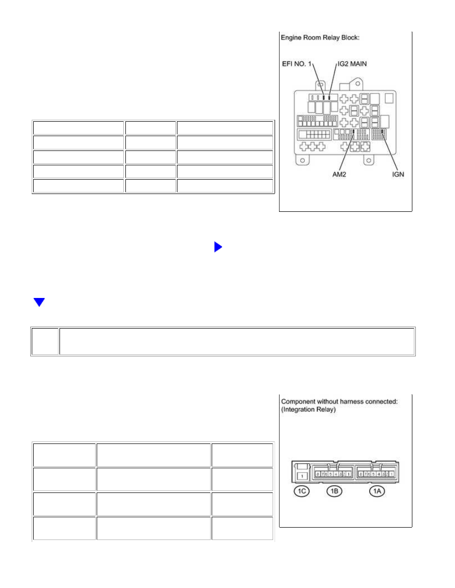
(a) Remove the AM2 fuse, IG2 MAIN fuse, EFI NO. 1 fuse and IGN

fuse from the engine room relay block.

(b) Measure the resistance according to the value(s) in the table

below.

Standard Resistance:

TESTER CONNECTION

CONDITION

SPECIFIED CONDITION

AM2 fuse

Always

Below 1 Ω

IG2 MAIN fuse

Always

Below 1 Ω

EFI NO. 1 fuse

Always

Below 1 Ω

IGN fuse

Always

Below 1 Ω

NG

CHECK FOR SHORT IN ALL HARNESSES AND

CONNECTORS CONNECTED TO FUSE AND REPLACE

FUSE

2.

INSPECT INTEGRATION RELAY (IG2, EFI)

(a) Remove the integration relay from the engine room relay

block.

(b) Measure the resistance according to the value(s) in the table

below.

Standard Resistance:

TESTER

CONNECTION

CONDITION

SPECIFIED

CONDITION

1C-1 - 1B-8

No battery voltage is applied to

terminals 1B-6 and 1B-7

10 kΩ or higher

1C-1 - 1B-8

Battery voltage is applied to

terminals 1B-6 and 1B-7

Below 1 Ω

1C-1 - 1B-4

No battery voltage is applied to

terminals 1B-2 and 1B-3

10 kΩ or higher

1UR-FE ENGINE CONTROL SYSTEM: SFI SYSTEM: ECM Power S...

OK

OK

TESTER

CONNECTION

CONDITION

SPECIFIED

CONDITION

1C-1 - 1B-4

Battery voltage is applied to

terminals 1B-2 and 1B-3

Below 1 Ω

NG

REPLACE INTEGRATION RELAY

3.

CHECK HARNESS AND CONNECTOR (ECM - BODY GROUND)

(a) Disconnect the ECM connector.

(b) Measure the resistance according to the value(s) in the table

below.

Standard Resistance:

TESTER CONNECTION

CONDITION

SPECIFIED CONDITION

D74-81 (E1) - Body ground

Always

Below 1 Ω

NG

REPAIR OR REPLACE HARNESS OR CONNECTOR

4.

INSPECT ECM (IGSW VOLTAGE)

1UR-FE ENGINE CONTROL SYSTEM: SFI SYSTEM: ECM Power S...

(a) Disconnect the ECM connectors.

(b) Turn the ignition switch to ON.

(c) Measure the voltage according to the value(s) in the table

below.

Standard Voltage:

TESTER CONNECTION

SWITCH

CONDITION

SPECIFIED

CONDITION

A24-28 (IGSW) - D74-81

(E1)

Ignition switch ON

11 to 14 V

NG

GO TO STEP 5

OK

REPLACE ECM

5.

CHECK HARNESS AND CONNECTOR (RELAY BLOCK - ECM, IGNITION SWITCH,
BATTERY AND BODY GROUND)

1UR-FE ENGINE CONTROL SYSTEM: SFI SYSTEM: ECM Power S...

OK

(a) Disconnect the ECM connector.

(b) Disconnect the ignition switch connector.

(c) Disconnect the cable from the battery negative (-) terminal.

(d) Disconnect the cable from the battery positive (+) terminal.

(e) Remove the AM2 fuse and integration relay.

(f) Measure the resistance according to the value(s) in the table

below.

Standard Resistance:

TESTER CONNECTION

CONDITION

SPECIFIED

CONDITION

A24-28 (IGSW) - 1B-8

Always

Below 1 Ω

1B-7 - Body ground

Always

Below 1 Ω

Positive (+) battery cable - 1C-1

Always

Below 1 Ω

Positive (+) battery cable - AM2 fuse

terminal 1

Always

Below 1 Ω

J9-5 (AM2) - AM2 fuse terminal 2

Always

Below 1 Ω

J9-6 (IG2) - 1B-6

Always

Below 1 Ω

A24-28 (IGSW) or 1B-8 - Body

ground

Always

10 kΩ or higher

Positive (+) battery cable or 1C-1 -

Body ground

Always

10 kΩ or higher

Positive (+) battery cable or AM2

fuse terminal 1 - Body ground

Always

10 kΩ or higher

J9-5 (AM2) or AM2 fuse terminal 2 -

Body ground

Always

10 kΩ or higher

J9-6 (IG2) or 1B-6 - Body ground

Always

10 kΩ or higher

NG

REPAIR OR REPLACE HARNESS OR CONNECTOR

1UR-FE ENGINE CONTROL SYSTEM: SFI SYSTEM: ECM Power S...


Content   ..  1303  1304  1305  1306   ..