Content .. 1299 1300 1301 1302 ..
Toyota Tundra (2015 year). Manual - part 1301
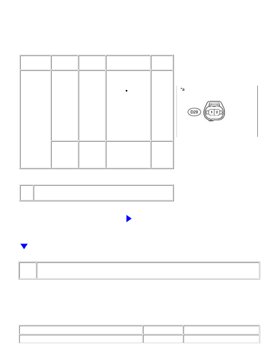
A
(a) Disconnect the purge VSV connector.
(b) Turn the ignition switch to ON.
(c) Measure the voltage according to the value(s) in the table below.
TESTER
CONNECTION
SWITCH
CONDITION
SPECIFIED
CONDITION
SUSPECTED
TROUBLE AREA
PROCEED
TO
D29-1 - Body
ground
Ignition
switch ON
11 to 14 V
Purge VSV power
source normal
Wire
harness
or
connector
between
purge
VSV and
ECM
A
Ignition
switch ON
Other than
result
above
Wire harness or
connectors between
purge VSV and
battery
B
Text in Illustration
*a
B
GO TO STEP 40
26.
CHECK HARNESS AND CONNECTOR (PURGE VSV - ECM)
(a) Disconnect the ECM connector.
(b) Disconnect the purge VSV connector.
(c) Measure the resistance according to the value(s) in the table below.
Standard Resistance:
TESTER CONNECTION
CONDITION
SPECIFIED CONDITION
D74-63 (PRG) - D29-2
Always
Below 1 Ω
1UR-FE ENGINE CONTROL SYSTEM: SFI SYSTEM: EVAP System;...