Content .. 1251 1252 1253 1254 ..
Toyota Tundra (2015 year). Manual - part 1253
OK
NEXT
(k) Connect the Techstream to the DLC3.
(l) Turn the ignition switch to ON and turn the Techstream on.
(m) Enter the following menus: Powertrain / Engine and ECT / Utility / Secondary Air Injection Check /
Manual Mode / AIR PUMP 1: ON, ASV 1: OPEN, AIR PUMP 2: ON, ASV 2: OPEN.
HINT:
When Manual Mode is selected, the Techstream initialization (atmospheric pressure measurement) is
performed automatically. The initialization takes 10 seconds. After the initialization, AIR PUMP and ASV
operation can be selected.
(n) Start the engine.
(o) Perform the AIR system forced operation while the engine is idling.
(q) Turn the ignition switch off.
NOTICE:
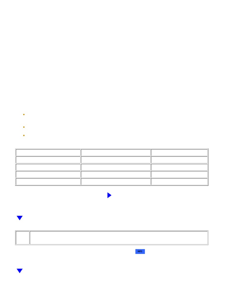
TESTER CONNECTION
CONDITION
SPECIFIED CONDITION
D50-4 (SIP) - D50-1 (E)
AIR PUMP: ON, ASV: OPEN
0.5 to 2 V
D54-4 (SIP2) - D54-1 (E2)
AIR PUMP: ON, ASV: OPEN
0.5 to 2 V
D50-4 (SIP) - D50-1 (E)
AIR PUMP: OFF, ASV: CLOSE
11 to 14 V
D54-4 (SIP2) - D54-1 (E2)
AIR PUMP: OFF, ASV: CLOSE
11 to 14 V
NG
REPLACE ECM
6.
REPLACE AIR INJECTION CONTROL DRIVER (FOR BANK 1 OR BANK 2)
(a) Replace the air injection control driver (for bank 1 or bank 2)
.
1UR-FE ENGINE CONTROL SYSTEM: SFI SYSTEM: P1613,P1614; ...