Toyota Tundra (2015 year). Manual - part 1192


  Index      Toyota     Toyota Tundra (2015 year) - Service and Repair Manual


Search            copyright infringement  


Content   ..  1190  1191  1192  1193   ..


Toyota Tundra (2015 year). Manual - part 1192


Last Modified: 9-16-2014

6.6 C

Doc ID: RM000002U1303YX

Model Year: 2015

Model: Tundra

Prod Date Range: [08/2014 -           ]

Title: 1UR-FE ENGINE CONTROL SYSTEM: SFI SYSTEM: P050A; Cold Start Idle Air Control System Performance;

2015 MY Tundra [08/2014 -        ]

DTC

P050A

Cold Start Idle Air Control System Performance

DESCRIPTION

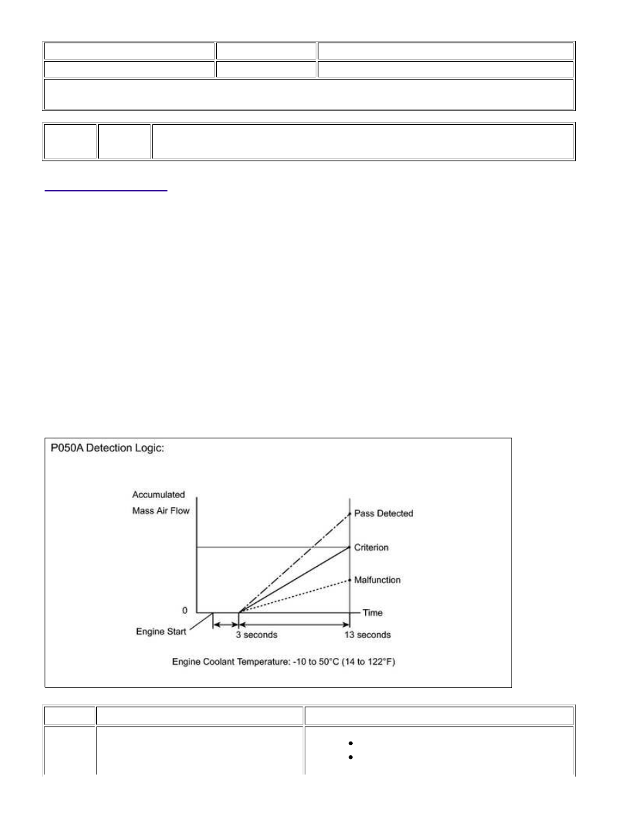
This monitor will run when the engine is started with the engine coolant temperature at -10 to 50°C (14 to

122°F). The DTC will be stored after the engine idles for 13 seconds (2 trip detection logic).

The DTC is designed to monitor the idle air control at cold start. When the engine is started with the engine

coolant temperature at lower than 50°C (122°F), the ECM measures the accumulated mass air flow at engine

idling. If it does not reach the criteria within 10 seconds, the ECM interprets this as a malfunction. The MIL is

illuminated and a DTC is stored when the malfunction is detected in consecutive driving cycles (2 trip detection

logic).

The ETCS (Electronic Throttle Control System) controls the idle speed. The ETCS operates the throttle actuator to

open and close the throttle valve, and adjusts the intake air amount to achieve the target idle speed.

NOTICE:

When the cable is disconnected from the negative battery terminal during inspections or repairs, the ISC

(Idle Speed Control) learning values are cleared. This DTC cannot be stored with the ISC learning values
cleared.

The ISC learning is performed when the engine is warmed up and has been idling for 5 minutes.

DTC NO.

DTC DETECTION CONDITION

TROUBLE AREA

P050A

Insufficient mass air flow at cold start

(2 trip detection logic)

Throttle with motor body assembly

Mass air flow meter

1UR-FE ENGINE CONTROL SYSTEM: SFI SYSTEM: P050A; Cold S...

DTC NO.

DTC DETECTION CONDITION

TROUBLE AREA

PCV hose

Air cleaner filter element sub-assembly

Intake system

VVT system

EGR valve assembly

ECM

Wire harness or connector

MONITOR STRATEGY

Related DTCs

P050A: Cold start idle air speed control system

Required sensors/Components (Main)

Throttle with motor body assembly

Required sensors/Components (Related)

Mass air flow meter

Engine coolant temperature sensor

Duration

10 seconds

MIL operation

2 driving cycles

TYPICAL ENABLING CONDITIONS

Monitor runs whenever

following DTCs not present

P0010, P0020 (VVT oil control valve)

P0011, P0021 (VVT system - Advance)

P0012, P0022 (VVT system - Retard)

P0013, P0023 (Exhaust VVT oil control valve)

P0014, P0024 (Exhaust VVT system - Advance)

P0015, P0025 (Exhaust VVT system - Retard)

P0016, P0018 (VVT system - Misalignment)

P0017, P0019 (Exhaust VVT system - Misalignment)

P006A, P0107, P0108 (Manifold absolute pressure)

P0101, P0102, P0103 (Mass air flow meter)

P0115, P0117, P0118 (Engine coolant temperature sensor)

P0120, P0121, P0122, P0123, P0220, P0222, P0223, P2135 (Throttle position

sensor)

P0125 (Insufficient Coolant Temperature for Closed Loop Fuel Control)

P014C, P014D, P014E, P014F, P015A, P015B, P015C, P015D, P2195, P2196,

P2197, P2198, P2237, P2238, P2239, P2240, P2241, P2242, P2252, P2253, P2255,

P2256 (Air fuel ratio sensor)

P0171, P0172, P0174, P0175 (Fuel system)

P0301 - P0308 (Misfire)

P0335 (Crankshaft position sensor)

P0340, P0342, P0343, P0345, P0347, P0348 (VVT sensor)

P0340, P1340 (Camshaft position sensor)

P0351 - P0358 (Igniter)

P0365, P0367, P0368, P0390, P0392, P0393 (Exhaust VVT sensor)

1UR-FE ENGINE CONTROL SYSTEM: SFI SYSTEM: P050A; Cold S...

P0401 (EGR system)

P0500 (Vehicle speed sensor)

P219A, P219B, P219C, P219D, P219E, P219F, P21A0, P21A1, P21A2, P21A3

(Air-fuel ratio imbalance)

Battery voltage

8 V or more

Time after engine start

3 seconds or more

Starter

OFF

ECT at engine start

-10°C (14°F) or more

ECT

-10 to 50°C (14 to 122°F)

Engine idling

3 seconds or more

Fuel-cut

OFF

Vehicle speed

Less than 3 km/h (1.875 mph)

Time after shift position

changed

2 seconds or more

Atmospheric pressure

76 kPa (570 mmHg) or more

TYPICAL MALFUNCTION THRESHOLDS

Accumulated mass air flow

Less than 106 g (varies with ECT)

CONFIRMATION DRIVING PATTERN

Connect the Techstream to the DLC3.

1. 

Turn the ignition switch to ON and turn the Techstream on.

2. 

Clear DTCs (even if no DTCs are stored, perform the clear DTC operation).

3. 

Turn the ignition switch off and wait for at least 30 seconds.

4. 

Turn the ignition switch to ON and turn the Techstream on [A].

5. 

Enter the following menus: Powertrain / Engine and ECT / Data List / Coolant Temp.

6. 

Start the engine and warm it up until the coolant temperature is the same as the coolant temperature

in the freeze frame data.

8. 

Idle the engine for 1 minute or more.

9. 

Enter the following menus: Powertrain / Engine and ECT / Trouble Codes [B].

10. 

Read the pending DTC.

HINT:

If a pending DTC is output, the system is malfunctioning.
If a pending DTC is not output, perform the following procedure.

11. 

Enter the following menus: Powertrain / Engine and ECT / Utility / All Readiness.

12. 

Input the DTC: P050A.

13. 

Check the DTC judgment result.

TESTER

DISPLAY

DESCRIPTION

NORMAL

DTC judgment completed

System normal

14. 

1UR-FE ENGINE CONTROL SYSTEM: SFI SYSTEM: P050A; Cold S...

A

HINT:

If the judgment result shows ABNORMAL, the system has a malfunction.

If the judgment result shows INCOMPLETE or N/A, idle the engine for 3 minutes, let the engine cool

down, and then perform steps [A] through [B] again.

15. 

If no pending DTC is output, perform a universal trip and check for permanent DTCs 


.

HINT:

If a permanent DTC is output, the system is malfunctioning.
If no permanent DTC is output, the system is normal.

16. 

INSPECTION PROCEDURE

HINT:

Read freeze frame data using the Techstream. Freeze frame data records the engine condition when

malfunctions are detected. When troubleshooting, freeze frame data can help determine if the vehicle was
moving or stationary, if the engine was warmed up or not, if the air-fuel ratio was lean or rich, and other
data from the time the malfunction occurred.

PROCEDURE

1.

CHECK ANY OTHER DTCS OUTPUT

(a) Connect the Techstream to the DLC3.

(b) Turn the ignition switch to ON.

(c) Turn the Techstream on.

(d) Enter the following the menus: Powertrain / Engine and ECT / Trouble Codes.

(e) Read the pending DTCs.

Result

RESULT

PROCEED TO

DTC P050A is output

A

DTC P050A and other DTCs are output

B

HINT:

If any DTCs other than P050A are output, troubleshoot those DTCs first.

B

GO TO DTC CHART

2.

READ VALUE USING TECHSTREAM (FUEL TRIM)

1UR-FE ENGINE CONTROL SYSTEM: SFI SYSTEM: P050A; Cold S...


Content   ..  1190  1191  1192  1193   ..